
SHADING GUIDE AND TIPS
Useful Links:
https://rmanwiki.pixar.com/display/REN/PxrSurface+in+Maya
https://rmanwiki.pixar.com/display/RFM/Pixar+Patterns
https://rmanwiki.pixar.com/display/REN/Using+Displacement
Feel free to explore this site and find useful examples.
MATERIAL TOOLS AND MENUS
Rendering Options – (Windows -> Rendering Editors -> Render Settings)
The most important settings will be under Common. You can set the resolution of your frames, image type, which frames it should render, which camera is used, and where the images are saved. Changing the quality of images can be done under the Sampling tab and changing the number of Max Samples. Rendering in Renderman is done in a separate application called “IT.” IT will open when you click Renderman -> Render or IPR Render. IPR render will constantly update and allow you to tweak texture properties and see how they’re changing on the fly.
Test Lighting
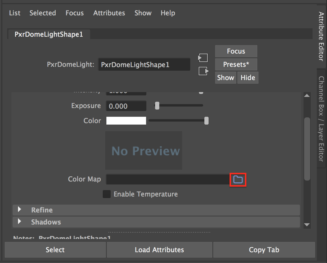
Since a large part of materials is figuring out how they interact with light, it’s important to test under lighting conditions similar to those in your short. A quick way to create test lighting is to use an environment light. Clicking the sun icon on the renderman shelf or going to Renderman -> Lights -> PxrDomeLight will create a giant sphere around your set which will project light inward. You can apply an image which will change the color and intensity of the light emitted from each part of the sphere. To do this, click the blue file icon next to the color map attribute in the attribute editor.
Hypershade (for more advanced shaders)
This is a special organizer which keeps track of materials you created and allows you to build more complex shaders with the node editor. To open a material in hypershade, select it in the scene or Material Browser and click this icon to see its connections.
Hypershade Icon
You can also find Hypershade by clicking on Windows -> Rendering Editors -> Hypershade.
Hypershade menu location
To graph a shader on the node editor, right click your shader and click “Graph Network”.

“Graph Network” button
Main window
This uses a “Node Editor” interface which allows you to build materials by passing values between blocks which perform operations or generate visual components.
Navigation
Alt+Middle Mouse allows you to scroll around the area (much like regular Maya). Alt+Right Click or Scrolling allows you to zoom in/out.
Making New Nodes
You can either dig for what you want using the drop-down Create menu or you can mouse over the main window and press Tab. This will allow you to start typing the name of a desired node and it will begin suggesting choices. This is a good way to explore and potentially find new, useful nodes.
Making Connections
If you just created a node, you will likely need to expand it in order to see what properties it can inherit or pass on. You can do this by clicking on the 3 horizontal bars at the top-right of the node.
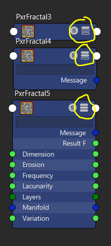
“Expand node” button
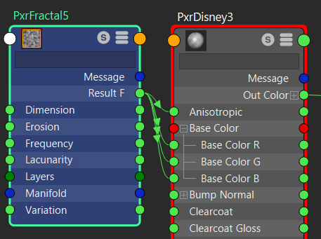
1 vs. 3 channels for black and white outputs
The circle on the left of a property denotes a potential input while the right side denotes a potential output. Many are double sided and allow you to forward useful inputs further down your graph if they become useful later. This has the added benefit of reducing clutter to you don’t have to wire something from the back all the way to the front. The color of these circles tries to clarify what kind of information that property works with. While Specular is perfectly happy at a value of 1, the Color property doesn’t know what to do with a single value and tends to look for 3 values (often Red, Green, and Blue). Keep an eye out for warnings on the bottom of the main window in case you give a mismatched data type.
If you want to pass a property from one node to another, simply click and drag from an output to an input. The connection forms an arrow to clarify the direction of information transfer. To keep things organized work left to right: your raw imported textures and nodes which give basic scaling information should be furthest left while the final, blue shader output should be furthest to the right.
Material Viewer
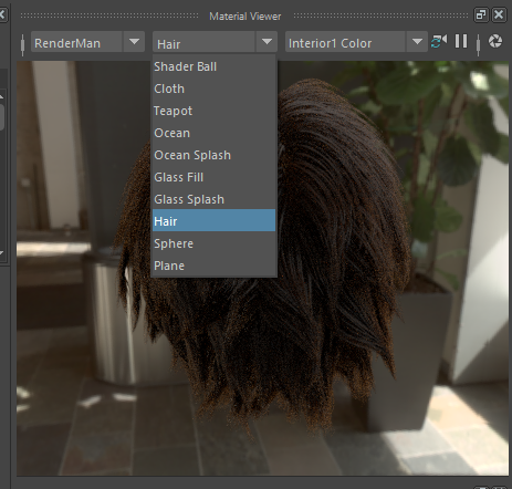
This is useful for checking changes in appearance as you play with values in the attribute editor and add new nodes. Make sure you are using an appropriate renderer (i.e. Renderman/Mental Ray/Maya Hardware) for the kind of shader you’re building. Watch out! The Material Viewer’s frequent re-renders can sometimes be a heavy burden on your PC. If things are slowing down, you may want to close this window and do manual renders when you want to check on things.
Material Browser
This keeps track of all the materials used in your scene. It allows you to quickly navigate your materials, open multiple simultaneously (with Shift), and apply them to selected objects/faces in your scene by middle-mouse-dragging them.
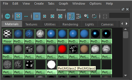
Material Browser
PXRSURFACE MATERIAL PROPERTIES
(!info)
Hovering your cursor over slider names in the attribute editor of Renderman materials tends to provide helpful definitions and examples of any attributes you may be confused about.
(!info)
Each PxrSurface shader has different properties you can modify: Diffuse, Primary Specular, Rough Specular, Clear Coat, Glass, etc. Each one of these properties has a Gain slider, which determines to what degree that property affects the material appearance of your object. For example, setting the Glass gain slider to 50% will make the material appear to be halfway transparent glass.
A detailed look at the important PxrSurface Properties:
Diffuse
Increasing gain on property will make your material look like an opaque, rough surface.
Color – This is the main color for your shader. While a single color can be selected, remember that an image or texture can be mapped in by clicking the checkerboard icon next to the slider.
Primary & Rough Specular
This refers to the material’s ability to reflect light. The smoother or shinier a surface is, the more light it will reflect. To control the shininess of your surface, adjust the Face color or Edge color attributes. Values close to 1 (white) will be as shiny as possible, while values close to 0 (black) will have no shiny highlights.
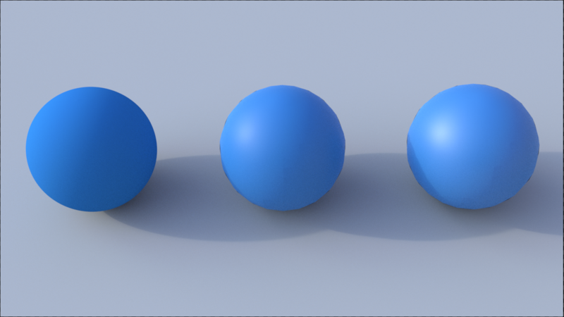
Specular Face color values of 0, .5, and 1
Roughness – This refers to a material’s ability to scatter and absorb light. Dull materials like rubber should have high roughness. Low roughness results in sharper reflections of the object’s surroundings.
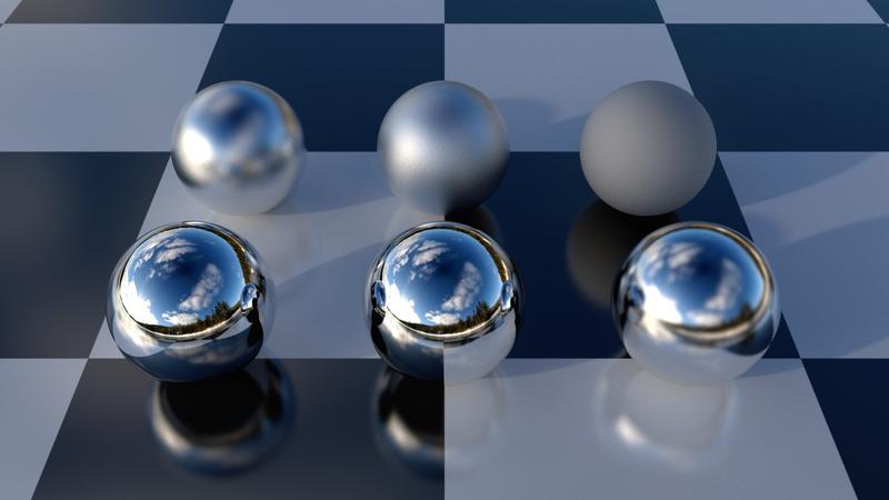
Roughness values (0 .2 .4) in the front row, (.6 .8 1) in the back.
Advanced -> Anisotropy – Most important when working with metals, anisotropy determines how specular highlights are distorted on the surface. In other words, it determines whether the shine is distorted as opposed to a perfect mirror. Extreme values of 1 and -1 work for materials like brushed metal. Negative values change the direction of the distortion.
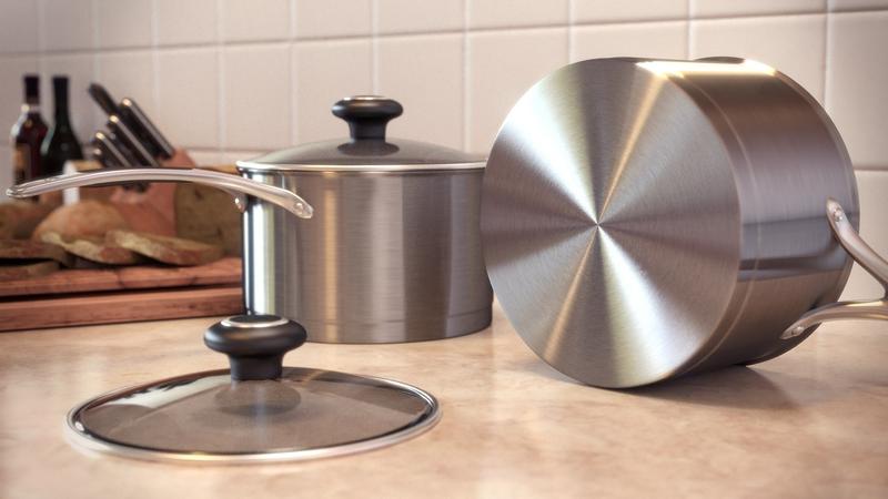
The light is stretched vertically on the left pot and radially on the right pot
Subsurface
This is used for waxy, translucent materials like skin or food. This can allow for more subtle, soft, realistic shaders where light can penetrate a little ways past the surface and bounce out with a different color. If you held a flashlight to your hand, the light would shine through as red in thinner areas. If you were to make a subsurface skin shader, you’d want your Mean Free Path color to be red while the main color would be a skin tone. You’d also want to adjust the Mean Free Path distance - this is the distance the light can reach through your object. Test subsurface shaders with a single, directional light source otherwise you won’t be able to notice the difference as the change would be applied equally across the object. Be careful, this property can lengthen render time significantly.
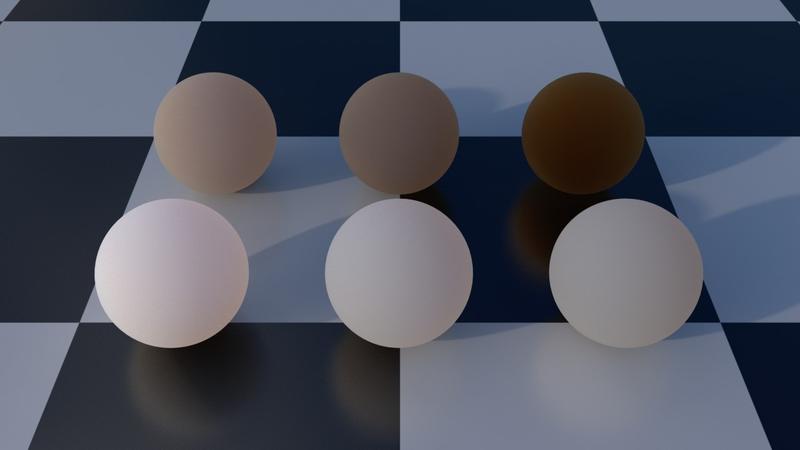
Glass
Glass can be used for not only glass itself, but also other transparent materials, like gemstones or water.
Refraction Gain – This allows you to change the amount of light that gets refracted through your material. If you want a glass that absorbs some of the light passing through it, like for a dark-tinted glass, set this value to <1.
Reflection Gain – This allows you to change the amount of light that gets reflected off of the surface of your material.
Refraction Color – This allows you to change the color of the light that gets refracted through your material. For example, to create grape soda you would set this attribute to a purple color.
Roughness - This lets you create roughness on the surface of your glass, like with frosted glass. To create an etched effect, add in a black and white image.
Globals
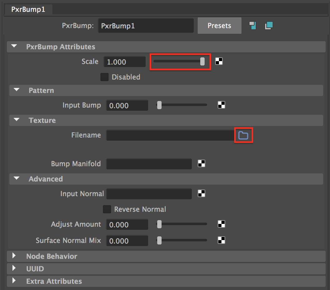
Bump – This allows you to add small grooves or bumps to your model. This won’t change the actual shape of your object but will make light behave as though there are grooves or bumps by changing the normals of your object’s surface. If you want to add small surface details, click on the checkerboard icon next to the bump attribute, and then click on Renderman->Patterns->PxrBump in the window that appears.

This creates a new bump map node. Now, click on the blue file icon next to the Filename attribute to add a texture or image file. To adjust the intensity of the bump effect, simply adjust the Scale slider.
Here is a demonstration of the effect a bump map can have on an object:
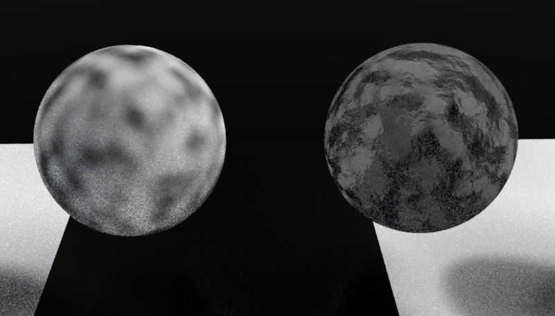
The same cloudy pattern is mapped to color (on the left) and to color & bump (on the right)
Presence – This determines how much of your object is actually rendered and works similar to opacity. Values between 0-1 will give a fake-transparency effect as some light will pass through. Instead, it’s better to attach a map to this node with values of 1 and 0 which can create a cutout pattern by removing portions of the object.
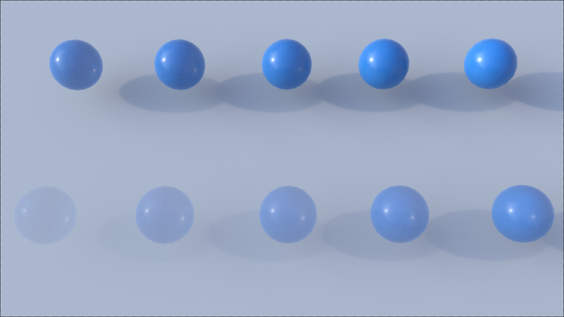
Presence value .1 on the bottom left and a value of 1 at the top right
Displacement This will change the actual geometry of your models to add shape, detail, or noise.
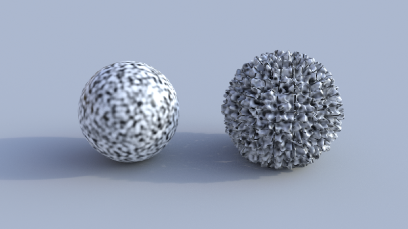
To add a displacement map, find the Shading Group node in the node editor. This is the node that your PxrSurface node is wired to, usually called something like “PxrSurface1SG”. Click on this node, and then click on the checkerboard icon next to “Displacement mat.” Now, choose Renderman->Displacements->PxrDisplace. This creates a Renderman displacement node. Now, click on this node, and in the attribute editor click on the checkerboard icon next to the Vector Displacement attribute. Choose Renderman->Displacement Patterns-> PxrDispTransform. This node allows you to control the strength of the displacement with the Displacement Height & Depth attributes. Finally, to wire in your displacement map image, click the checkerboard icon next to the Vector Displacement attribute, then click on file and choose your file. Your node editor setup should now look something like this:

This will undoubtedly require some tweaking, so adjust the Height & Depth values in the PxrDispTransform node to your liking. Make sure to do test renders, since displacement doesn’t show up in the viewport. Also use caution since detailed displacement maps add lots of render time.
USEFUL PATTERNS AND OPERATIONS (in Renderman)
File (Texture) – This allows you to bring in images you’ve made and wire them into nodes
Fractal Noise (Ex. PxrVoronoise, PxrFractal, PxrFlakes) -Octaves/Layers – This will overlay repeated iterations of your fractal and help blend the noise - can help make things less grainy and make the resulting fractal more dense
PxrBlend/PxrMix- Take in two color or map inputs and combine them. PxrMix has a property where you give it a range between 0-1 (or an array of values between 0-1 from a fractal). The will apply the more of the first input where there are values closer to 0 and more of the second input where the values are closer to 1. PxrBlend gives you the choice of several operators which you might recognize from image software like photoshop. In Blend, the alpha layer will help it determine how much of each input is applied.