INTRODUCTION
Welcome to the Hard Surface Modeling Lab!!
Several things to note: hard surface modeling refers to non-organic models (i.e. furniture, architecture, objects, etc.) as opposed to organic modeling, which refers to character modeling and landscape modeling. Organic modeling tends to involve more sculpting than hard surface modeling. Hard surface modeling involves more edge manipulation and face extrusion.
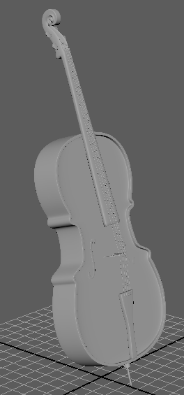
This lab will walk you through the process of modeling a cello. It involves 3 major techniques of modeling: box modeling, contour modeling, and modeling with curves. This is a DIFFICULT lab! Start on this early! There are many parts to it and it can get complicated. I tried to include as many screenshots as I possibly can for clarity’s sake.
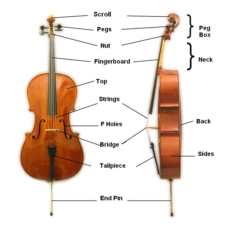
Before we begin, familiarize yourself with this labeled diagram since I’m going to be using these terms to refer to parts of the cello.
Outline
- Modeling the Cello Body/Frame
- Modeling the Fingerboard
- Modeling the Tailpiece
- Modeling the Cello Bridge
- Modeling the Strings
- Modeling the Scroll
- Connecting the Scroll to the Cello
- Modeling the F-Holes
- Modeling the Final Components (fine tuners, tuning pegs, endpin)
- Final Adjustments
MODELING THE CELLO BODY/FRAME
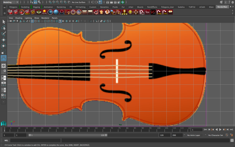
Import this image of top-down view of cello in the “top” orthographic view in the viewport window.
Tip: Before I start any modeling I always like to bring my reference images on an image plane and put them on a separate layer. That way I can turn visibility off and on whenever I want.
The first important tool we will be using is called the CV Curve Tool
This tool allows you to draw curves in Maya (the same way you might in Adobe Illustrator or a similar program) and create geometry from those curves. As a result, this tool becomes very helpful in modeling smoother/curvy objects like a cello body.
Go to Create -> Curve Tools -> CV Curve tool. Trace the outline of the cello body (just the frame, nothing else).
Since we can make our lives easier by duplicating/mirrororing curves, trace ONLY HALF of the cello, so choose the left side/right side.
When tracing the outline, try not to click on points that are on the same longitudinal line, otherwise they’ll be overlapping edge loops once you connect both sides using the multi-cut tool. The curve I made looks something like this -
Duplicate the curve (command + d) and move it up to the desired thickness of the cello.
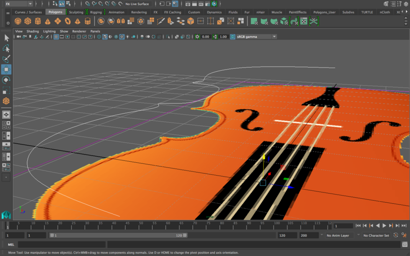
Select both curves, go to Surfaces—>Loft and click the option box. These should be your options -
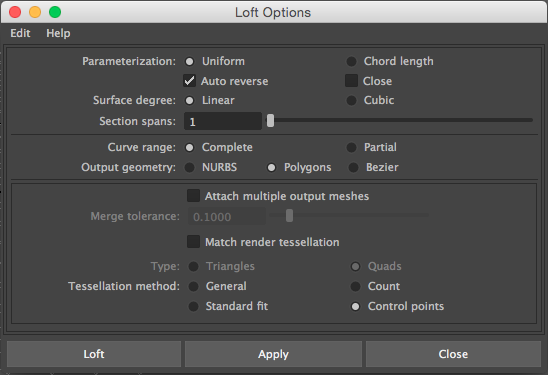
KEY OPTIONS TO NOTE
Surface degree: linear
This inserts edge loops between the top and bottom of the lofted surface. If this is set to linear, there will be no edge loops and there will only be single faces stretched between the top and bottom edges. If you want more edge loops, increase the “section spans” number.
Output geometry: polygons
Polygons are much easier to work with and edit, so we’ll stick to polygons.
Tessellation method: control points
What this option asks is: where should I place the vertices that define the shape of the curve? This option gives you maximum control over the vertex/edge placement of this curve since it will make a vertex with every click you made while tracing the curve.
Click apply and you should find a cool looking mesh new stretched between the two curves. This will be the side of the cello. If you don’t like the thickness of it, undo and alter the height of the curve and loft again.
Mirror geometry on the cello. You should end up with this
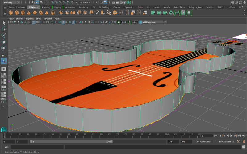
Merge vertices along the bottom stitch to make sure the two sides are connected
Connect the upper gap together by using the append to polygon tool
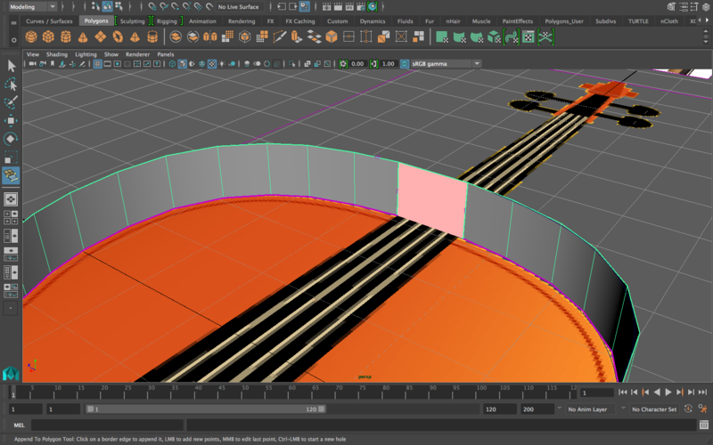
If you click on the CV curves you made and move them around, you’ll notice how they change the body of the cello. We don’t need this anymore, so let’s delete the curves. Now the mesh can only be altered through altering its faces/edges/vertices like a normal polygon.
If you double click the upper or lower edges, only that ring of edges should be selected. If both are selected, it means that there are still some disconnected edges in the mesh. Double click on the bottom edge, and go to Mesh—>Fill Hole. It should look like this
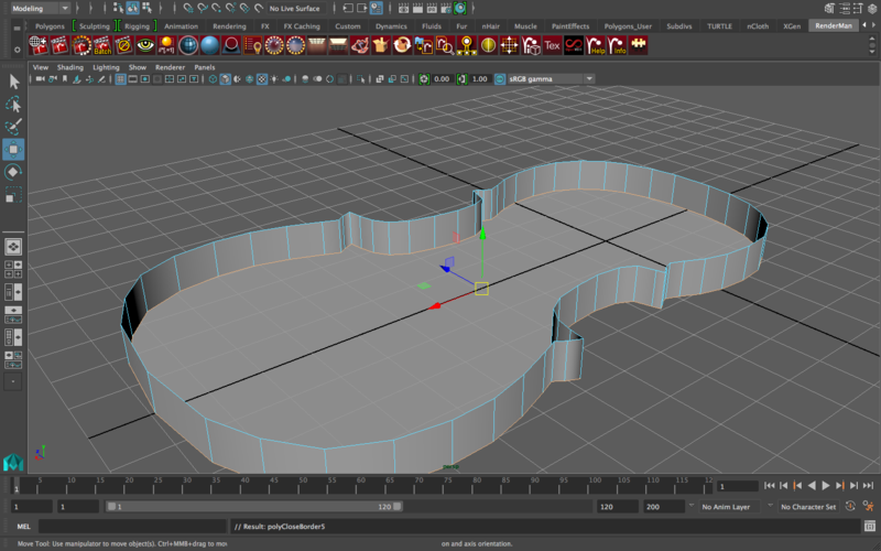
At this point, it might be useful for me to add my cello body onto a layer of its own. That way I can also toggle the visibility of the body the way I do with my reference images. To do this, open the channel box/layer editor. Then, select the object (or the image, or whatever it is you’d like to add to a layer) and go to Layers—>Create Layer From Selected. Then a “Layer1” will be created. If you click on the “V” button, that layer’s visibility is going to be turned off. Rename the layer to something that makes sense.
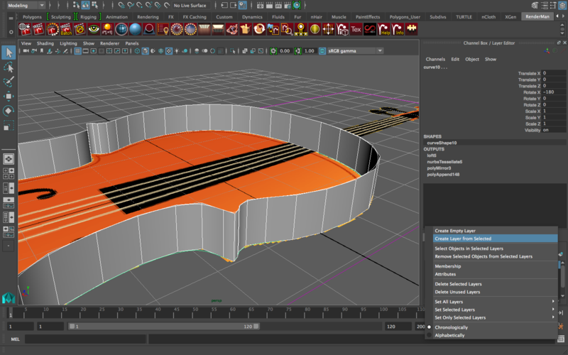
Now back to the modeling!
Our cello body currently looks kind of okay the way it is. There is, however, a major problem: the edges on the side of the cello do not flow through it! Want to see why this is bad? Click on the cello body, and press “3” to smooth.
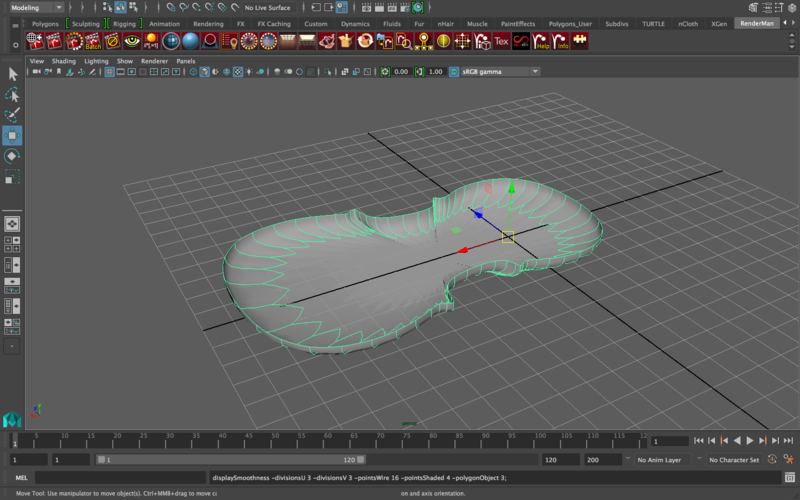
Yuck! This goes back to the idea of having good edge flow and good topology. Right now, our edge flow is interrupted at the bottom face (and quite honestly terrible), and as a result the bottom face has WAY more than 4 vertices (which is something we never want). Let’s fix that.
Go to Mesh Tools -> Multi Cut tool. Using the multi-cut tool, connect all the edges across.
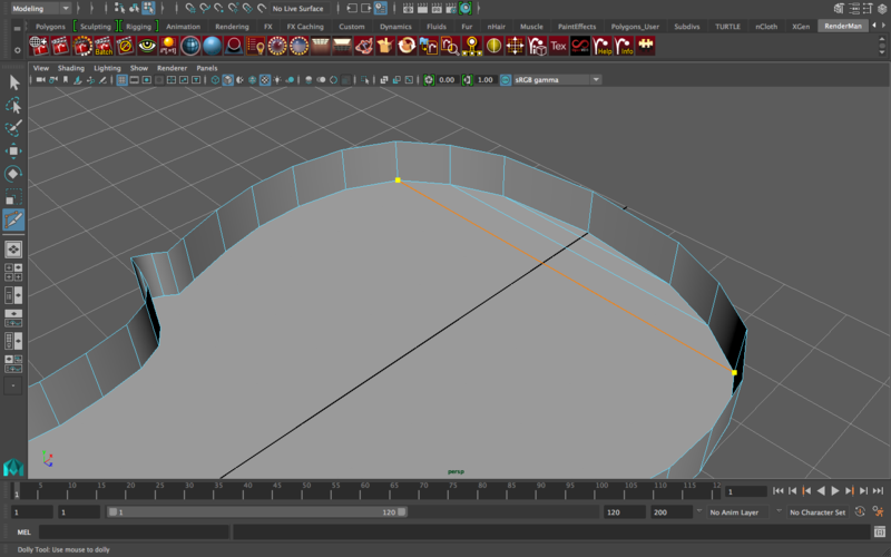
Okay, here’s an interesting situation that happened to me that might have also potentially happened to you depending on the clicks you made when tracing the CV curve.
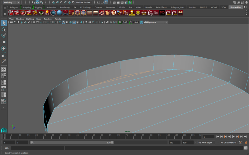
Do you see that triangle? This is bad. Quads and triangles do not go together! The whole model should be in quads, or it should all be in triangles, but no mixing between them. Here’s how I’ll fix this:
Go to Mesh Tools—>Insert Edge Loop and click the option box.
Make the edge loop “multiple” instead of “relative” and make the number of edges “1”
Click on one of the many horizontal lines you just created when connecting the sides of the cello, and a vertical edge loop will run down the middle of the cello but it will stop near the end.
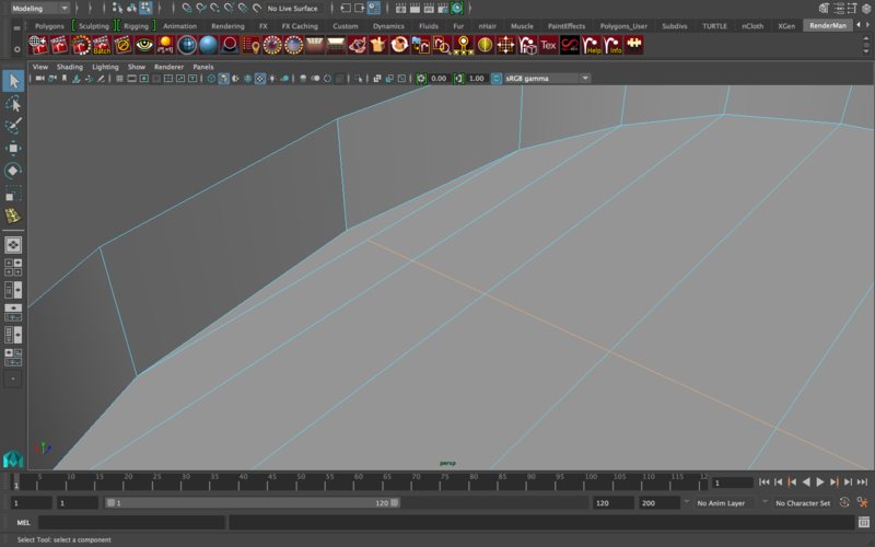
Now, delete the triangle.
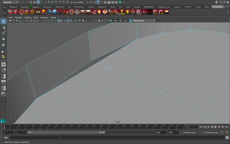
Go into vertex mode. Click the vertex in the middle (on the inside of the cello) and, while holding “v” (that’s the “snap to vertex” option), move the vertex on top of the other one. It should snap in place like this
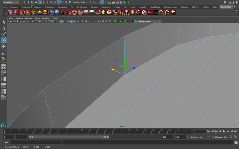
Even though it looks complete, it isn’t because the vertices aren’t merged yet. Click and drag (make a small box) around the vertices and go to Edit Mesh—>Merge.
Now when you smooth, it should look wrinkle-free.
We’re going to extrude in order to give the cello its proper outline.
Select all the faces on the SIDE of the cello
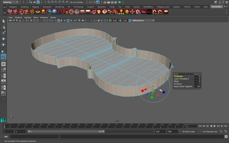
Then extrude, and ONLY use the yellow arrow (or the equivalent of that arrow included in the screenshot above) to pull these faces out. The reason we only need that arrow is because we don’t want the faces to get bigger as we pull them out, we just want them moved out.
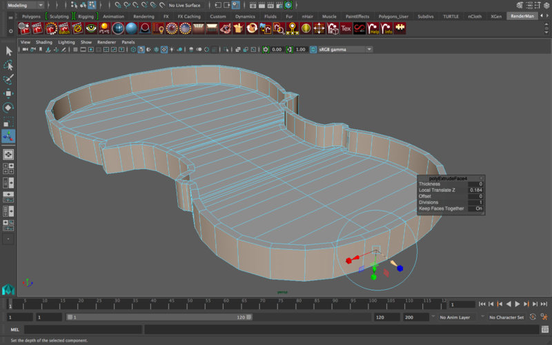
Delete the upper lip created as a result of the extrude. Delete these faces
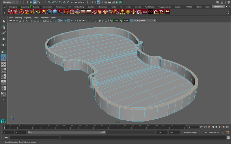
So now we have the correct outline and shape of our cello body, however, the biggest problem right now is that our cello is hollow when most functioning cellos should NOT look like that. (This is where reference images come in handy). To fix our follow cello, we are going to do a few tricks!
Add one edge loop going through exactly the middle of the cello body like this
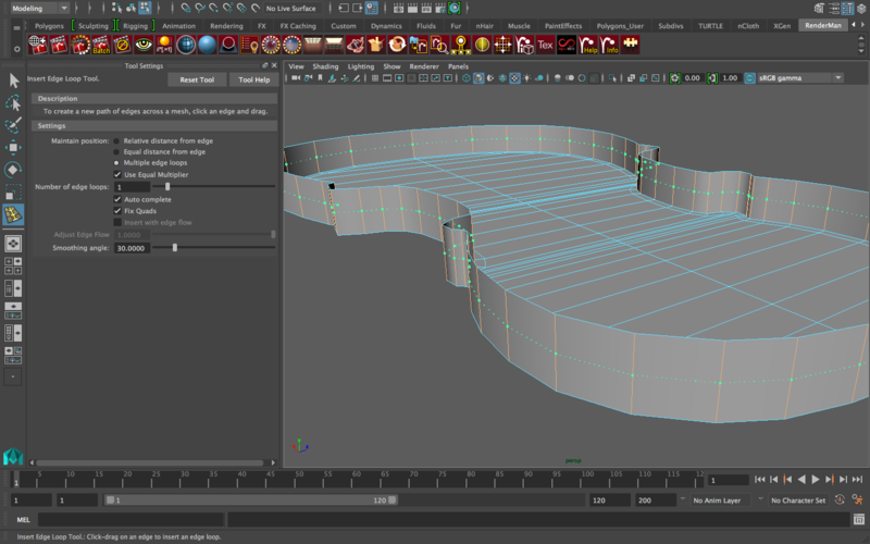
By doing so, we have split our cello body into two halves: “the upper half” appears hollow, while the “bottom half” looks covered. We want BOTH sides to look covered, so we are going to delete the upper half of the cello and then Mirror Geometry to fix this.
Delete the entire upper ring of faces of the cello (shift click one face and then double click the one after it and the whole row should be selected).
Now we’re going to extrude the bottom faces to give a slight indent in the cello (a nice detail to add.) Select all the faces in the middle of the cello (leaving the outer faces) and extrude the faces upward, just by a bit. Here’s how much I extruded
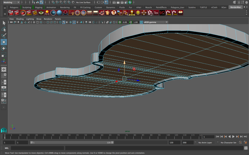
Before moving on to the next step, (1) delete history, (2) freeze transformations, and (3) Modify—>Center Pivot. If you don’t do this, chances are that the mirroring (the next step) will screw up. (Remember the shortcut buttons to each of these actions)
Now go to Mesh -> Mirror
Mirror the cello in the positive y-axis to have both sides of the cello body.
Make sure in the option box you have selected “Merge Border Vertices” and to double check afterwards that all the vertices are connected.
Resize thickness depending on how thick you’d like the cello body to be.
Edit any vertices you don’t like. Since the outline of this cello is based on a curve, and every point of the curve is hand-placed, there’s bound to be areas too sharp/too smooth, so go ahead and edit the location of some vertices. If you’d like, you can edit one side, delete the other side, and mirror geometry. There’s bound to be many differences between your CV curve and the one I made, so this is a step in which you should edit the edges/vertices depending on what you have to make it look smoother.
If you press “3” notice how some parts (specifically the frame) look too smooth. To fix this, I’m going to add edge loops to reinforce the angles. Here are the edge loops I’ll add
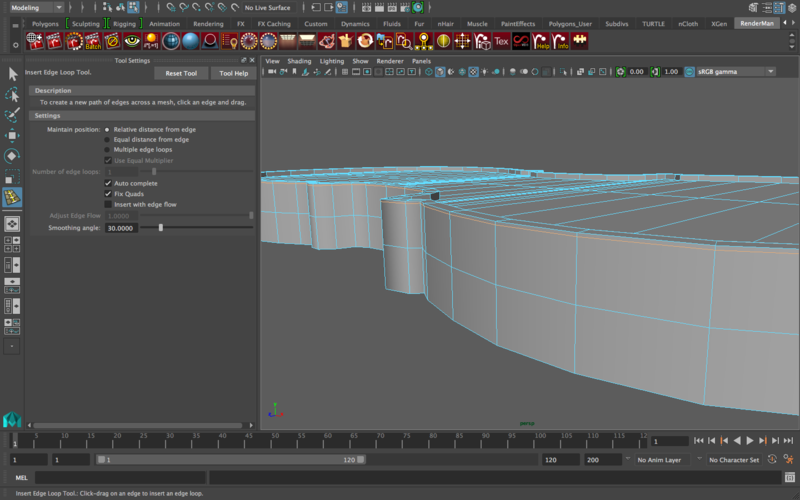
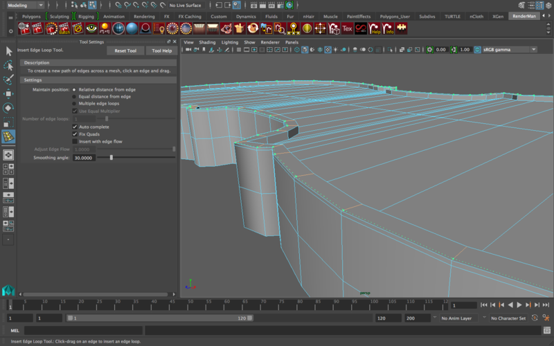
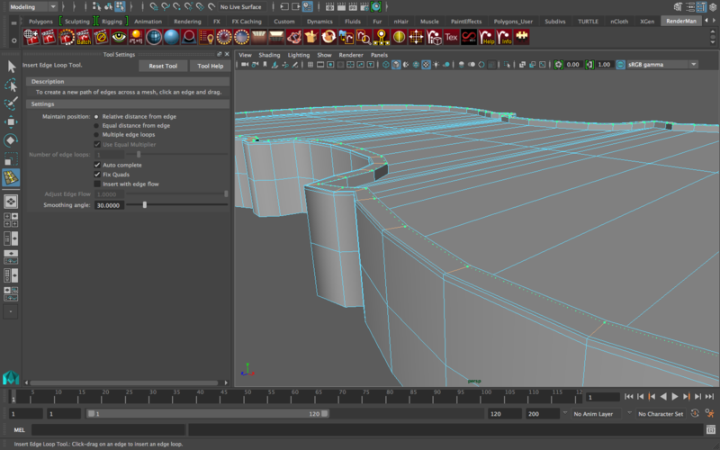
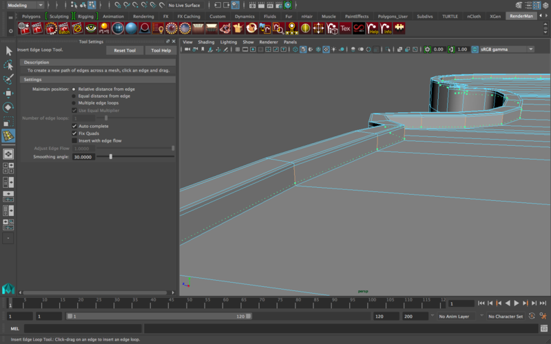
Now if you smooth, look at how much more solid the outline looks like
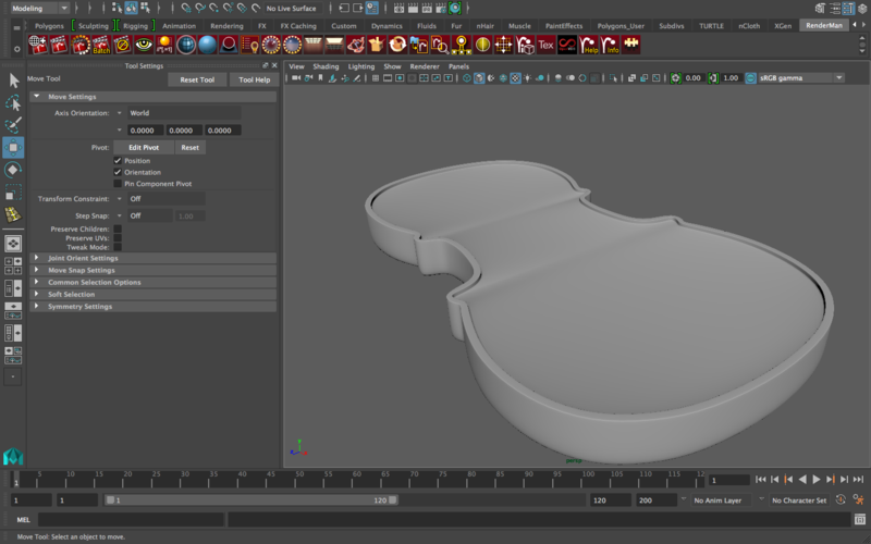
However, we did all this to the upper half. So let’s delete the lower half of the cello (the lower mirror) and we’ll mirror geometry later when we’re ready. But we’re not quite ready just yet.
There’s still a pretty obvious problem: these wrinkles are ugly
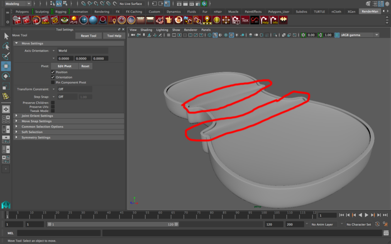
Take a look at the edge loop: the wrinkles are where there are many more edge loops than the rest of the cello, because these parts of the mesh are more reinforced/emphasized than the rest, and so this difference causes wrinkles. How do we fix this?
Three potential strategies to fix the wrinkles:
Potential strategy one: remove edge loops.
If you remove a few of the edge loops around the wrinkles, it’ll get smoother there but you are going to lose some of the smoothness of the curvature of the sides, potentially ruining the cello’s outline. Careful edge loop removal might work in some instances though.
Potential strategy two: separate the side of the cello from the front and back sides.
Sneaky! The idea behind this is that the cello front and back side don’t need to be attached to the cello frame/sides, so then there would be no need for an edge flow to go from one end of the cello to another. Then you can delete any edges that wrinkle up the model with no worries about losing curvature of the frame. HOWEVER, there are potential disadvantages: if you want to animate the cello cartoonishly (i.e. the body bends/twists) it needs to be one object. Also, if the edges are different enough, it actually won’t match perfectly (there will be unwanted gaps/intersections).
Potential strategy three: ADD edge loops
What? Add? Yes! The reason for the wrinkles is the sudden DISCREPANCY in the rate of edge loops. They’re spaced out relatively evenly, and then all of sudden there’s a bunch of them in a really tight space. To smooth out this difference, we can add more edge loops relatively close to the wrinkly areas and the discrepancy should not be that bad. This can work wonders in removing these ugly wrinkles.
Which strategy to choose?
Honestly, this to me is part of the joy of modeling: when the task is difficult enough, it reaches a point where you need to make decisions that involve compromises, and that totally depends on what you want out of your model. Each option is totally legitimate, it’s just up to you which disadvantages you choose to live with, but the final goal is the same: fixing the wrinkles of the cello body.
For the purpose of this tutorial, I’m going with the third strategy. Let’s add two vertical edge loops on one side. I’m not going to use the “multiple” option under the edge loops settings because I want manual control over edge placement. Here’s where I’ll put the edges
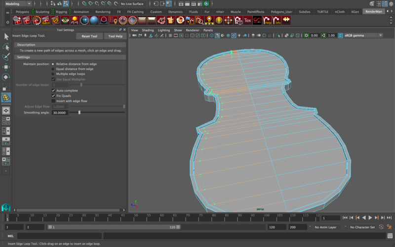
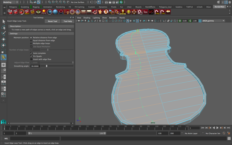
If you go into smooth mode (press 3 while object is selected), the wrinkles on the left side are pretty much gone! HOWEVER, as with many situations in modeling, the fix I made in one part caused a new problem somewhere else. Look at this jagged part of the bottom of the cello that wasn’t there before (it’s also on the top)
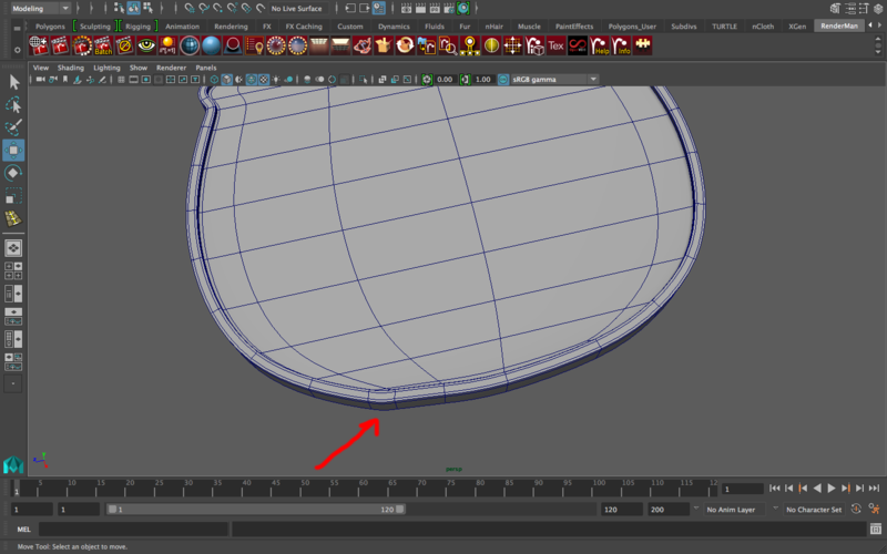
Notice how the jaggedness is caused by a similar problem to the wrinkles: there’s two edges extra close to each other. To fix this, I’m going to delete one of the edges that, now with two new edge loops we made, actually isn’t necessary anymore. I’m going to delete this edge
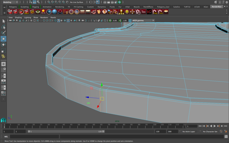
Make sure when you double click and delete the edge, you then go into vertex mode and delete its vertices as well! Otherwise, they’ll still be there and the shape of the cello will not change. Alternatively, you can hold the ctrl button as you double click on the edges and press the backspace/delete button and that will delete the edges + the vertices.
Look how much better it is now
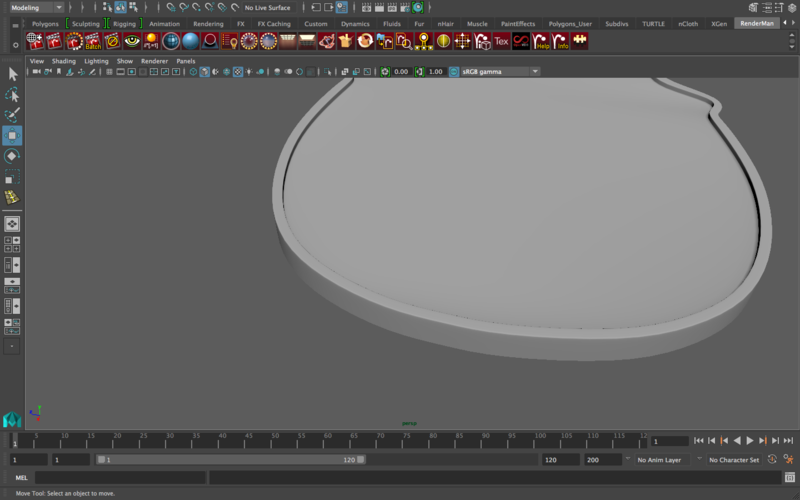
Now do the same thing for the upper corners of the cello.
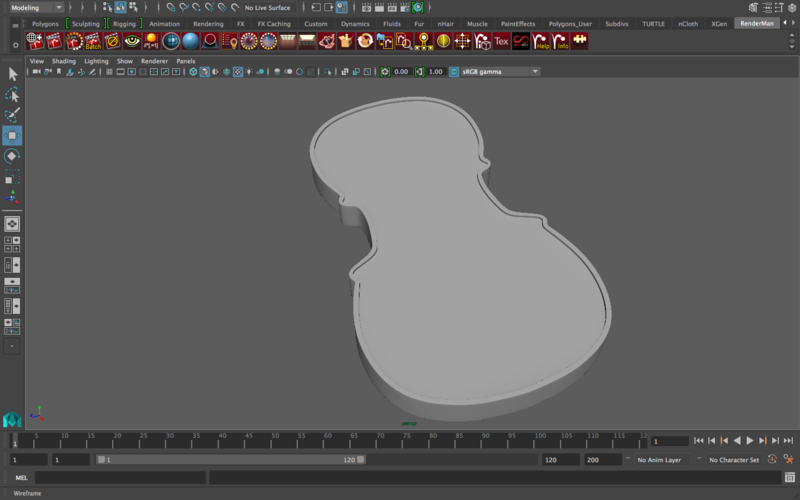
Now that we’ve fixed one side of the cello, just delete the other half (the one you did not edit) and you’ll end up with a remaining quarter of a cello. Mirror it across and then mirror that to the bottom/top depending on which side you were working on. Merge all vertices. Now you should have a full cello body!
MODELING THE FINGERBOARD
Hide the cello body that we’ve worked on so far (click the “V” button on the layer we made earlier)
Create a polygon cube, and match it to the cello’s fingerboard. Something like this
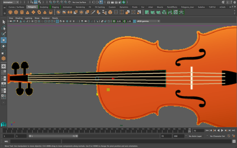
We are missing something essential, however: the side view. The shape of the fingerboard is correct, but we need to get it to be at the correct angle off the cello.
Import this image into the front view of the orthographic view in maya.
Adjust the image accordingly. Make the cello in it the same size as the cello you modeled, and it’s okay if you need to stretch it beyond what’s usual since we’re only focusing on the angle. It is up to you how/if you want to change the proportions of the cello when you’re done with it. Since we used a 2d image (hand drawn) for the cello body, the body outline is going to be really precise. However, since this is an image of an actual cello, the perspective isn’t going to be “flattened” and so it’s okay if there are discrepancies. We’re not going for a picture-perfect cello, just a really good model.
Match the fingerboard angle to the one in the image
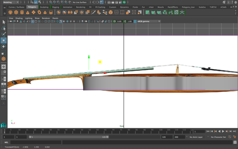
The thickness of the fingerboard will change later as the model comes together. Also, you can add edge loops now so that it is smoothed if you choose to smooth it. Personally I prefer to leave these final touches until the end in case major changes happen to the model, but by all means go ahead and edit that now if you like.
MODELING THE TAILPIECE
This is the same process as the fingerboard. Go into the top-down view, and, starting with a cube, match the shape of the tailpiece
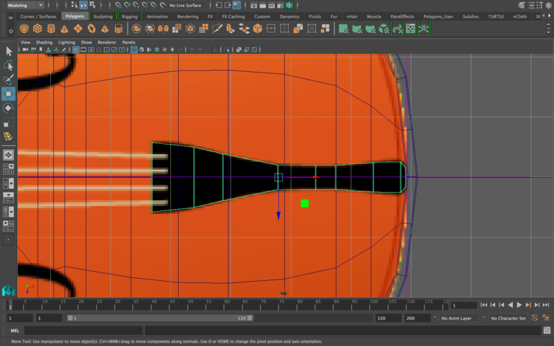
When you’re done with that, use the side image to get the angle of the tailpiece correct as well
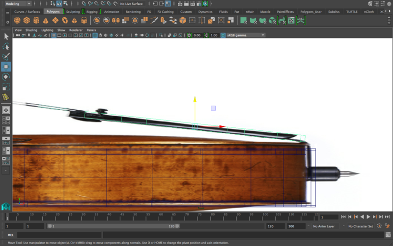
If you haven’t already, I’d recommend putting all of your modeled pieces in different layers.
MODELING THE CELLO BRIDGE
This is going to be a lot more complicated than the fingerboard and the tailpiece, so for the sake of simplicity, hide everything you’ve modeled so far (using those great layers you made earlier).
Import this image and place it in the the “top” view of the orthographic views
It doesn’t really matter what size the image is since we’re going to resize the whole model when we’re done with it anyway, just keep in mind that if/when you resize it, you resize it in all dimensions so that it remains in proportion.
We will NOT use curves to model this. Why? Because when you reach this stage, it’s going to be pretty much impossible to get any semblance of a good edge flow using the multi-cut tool
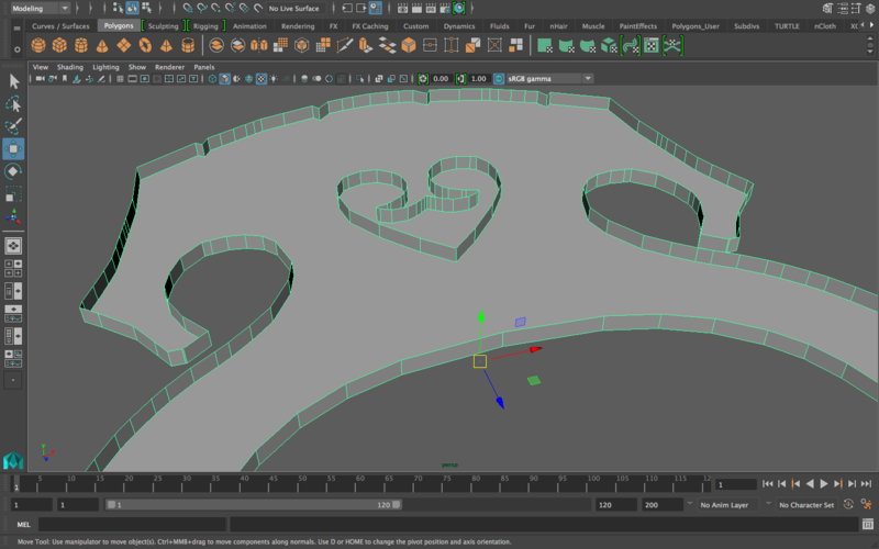
Connecting all these edges by cutting between them? Yeah…good luck with that.
So one of the more intuitive ways of modeling this object is using contour modeling. This technique involves starting with a plane, and then extruding edges and moving vertices to get the plane to look like the object. So, let’s start with a plane on one of the cello bridge’s legs
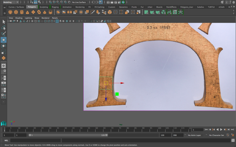
By extruding the top edge, moving it up, adjusting its width, and then extruding again and doing the same thing again, you can work your way through the model. For example, several steps later you’ll probably find yourself around this stage
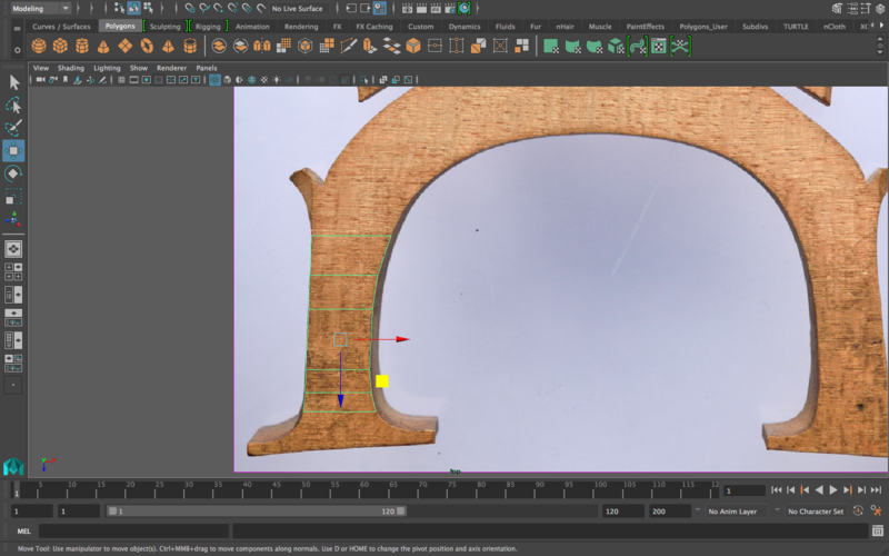
And it’s pretty much this process all throughout the model. Same as with other models, I’m just going to focus on one side, and then when I’m done, I’ll just mirror the geometry. After following this process for one half of the bridge, you should end up with something like this
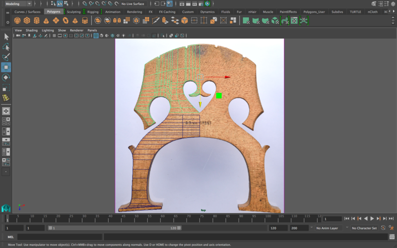
All of this literally started with one plane. All I did was extrude, edit edges and vertices, and extrude again and keep going. As you might notice, I broke it into two segments. I just personally found that easier as an approach than to try to keep it one object (it was just easier to visualize, and things got tricky as I approached the really rounded areas like the heart shape in the middle). You can split this into as many different segments as you like, as long as they’re all connected in the end with consistent edge flow. Also, I didn’t include many in-betweens because this will probably look different for you than it will for me, so I just thought I’d communicate the main idea.
As is usual, once the segments are connected, mirror geometry to get the other side of the bridge and merge vertices as needed
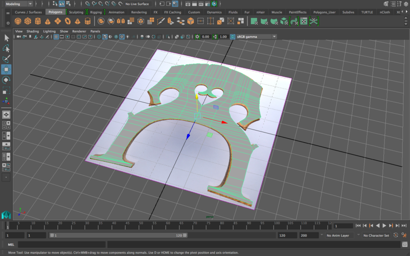
Since we started with a plane, you’ll notice that the bottom of the bridge might have black faces which means those normals are “reversed”. To fix this, all we need to do is select our bridge in object mode and then extrude upwards. You can extrude as far up as you need to get the thickness you like.
Once you have a thickness you are satisfied with, try smoothing out the bridge. It looks okay, but it’s still too smooth to look like a solid object. For that, I’m going to place several edge loops in multiple places to reinforce the 90 degree angles. The closer you place an edge loop to a 90 degree angle, the more that angle will be emphasized. Here’s where I’m placing the edge loops
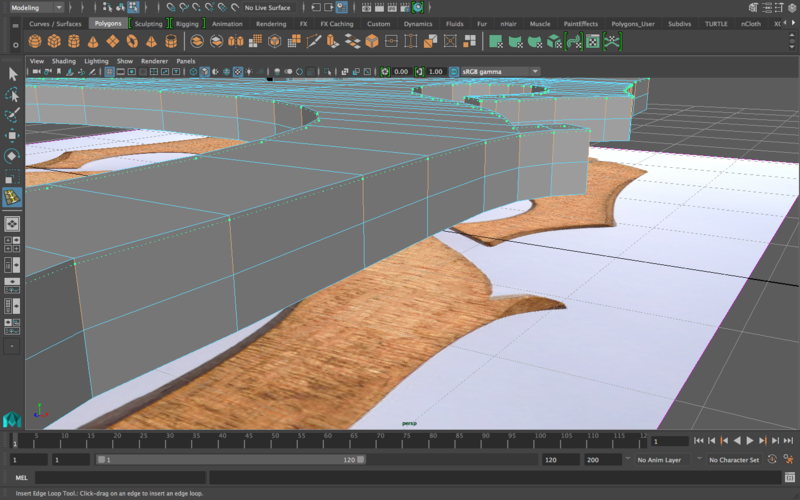
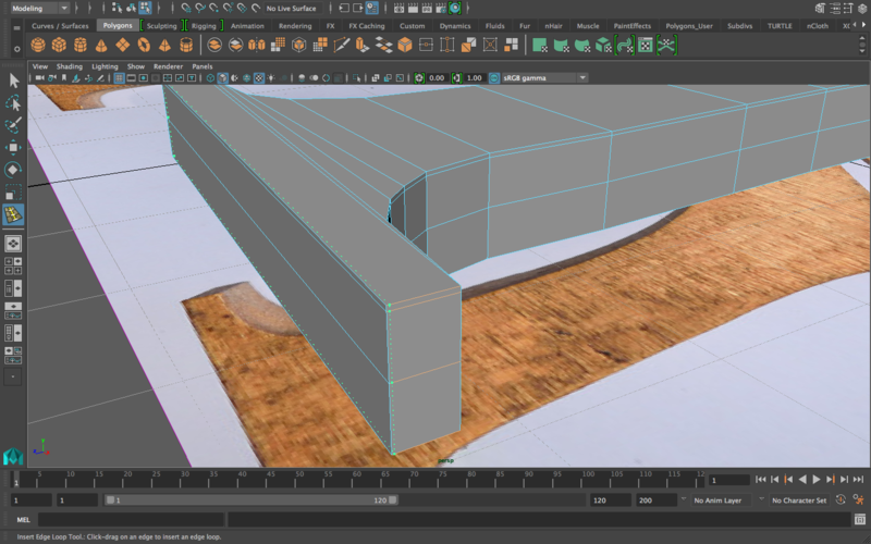
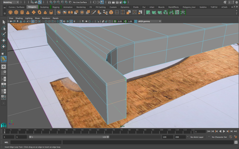
Smooth and unsmooth as you do this to check your progress: is the model looking better/worse? Adjust accordingly.
Using the help of the reference images, place the bridge in its correct position on top of the cello body. Here’s what it looks like for me
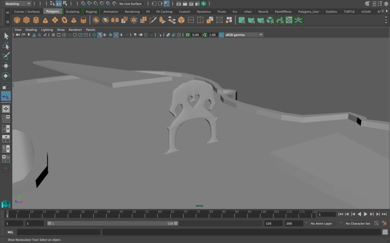
MODELING THE STRINGS
If you take a look at any side image of a cello, you’ll notice that the purpose of the bridge is to support the strings and create the tension needed to create enough vibration on the strings so that the cello can actually produce sound. At that point where the strings are stretched off the bridge, they’re flat. So let’s start there.
Make four cylinders, one for each strong. Place them at the four nooks in the bridge

Go into face mode for all four cylinders. Select the ends that are on the side of the tailpiece, and extrude these ends all the way to the beginning of the tailpiece (use the reference image’s help for placement). It should look something like this
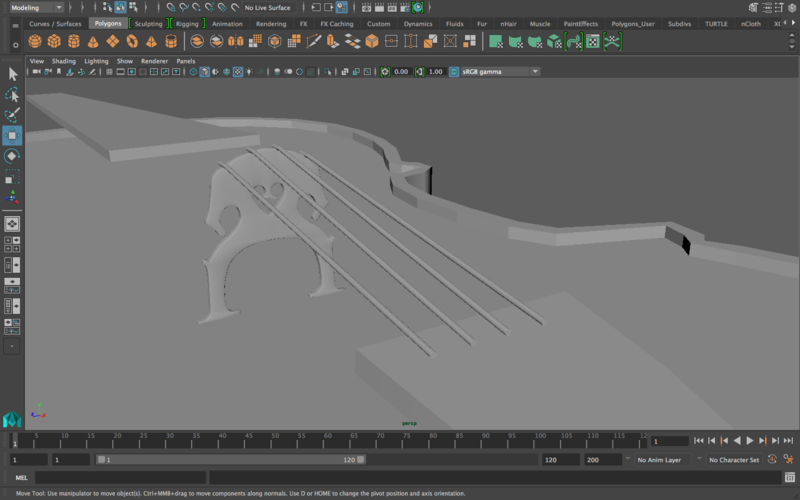
Now let’s work on the other side. Do the same: extrude the faces of the other ends and drag them all the way up to the end of the fingerboard. Use the reference image for help in positioning them. Don’t worry about stretching them after the fingerboard just yet, we’ll get back to them when we finish modeling the scroll.
To add a little bit more realism, push the ends of the strings at the end of the fingerboard closer to each other. Generally, strings aren’t equally spaced out throughout the length of the cello. Plus, you’ll need to do this anyway later since the scroll isn’t going to be wide enough for the current spacing of the strings. This is what the strings should look like for the moment
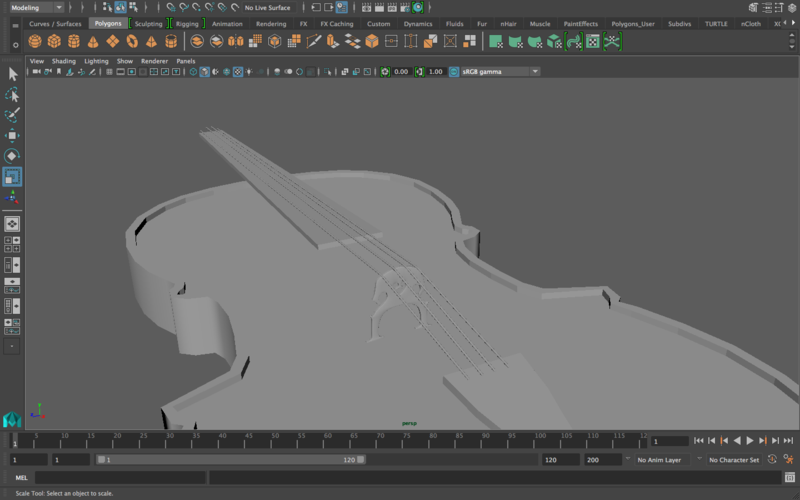
MODELING THE SCROLL
Warning: imminent insanity. This is the most difficult part of the lab. It’s also the most creative, so this should be a weird combination of really difficult and yet really interesting. Follow along with the general idea, don’t worry about clicking exactly where I’m clicking: curves are hand-placed, so it’s not realistic to assume that you’ll have the exact same results as me.
Basically, we’re going to use curves to trace separate layers for the cello’s scroll. Then we’ll loft the curves, connect the segments using a variety of tools (merging vertices, appending to polygon, etc.) to end up with good edge flow and to make sure that we don’t have any triangles.
Let us begin.
Import this image and place it near where the scroll would be relative to your model. Also, resize the image to kind of get it to be similar in size to what it would be in the final model
cello_scroll.zip
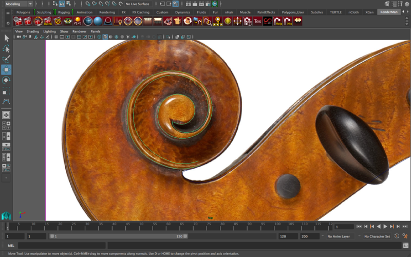
Using the CV curve tool, start by tracing the first curve: the outer outline of the scroll. This is what I mean by the outer curve/outline (the curve is colored in green)
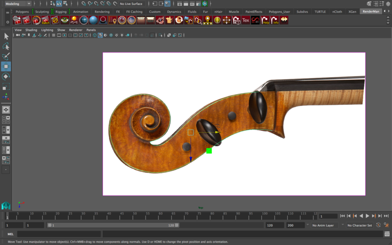
Then, once you’re done with the outer curve, use the CV curve tool to trace the inner curve. It is necessarily going to be awkward to choose the start and end points, considering that the final object is so seamless that it doesn’t seem to have any start/end points, but just choose them and we’ll blend the two segments together near the end anyway. This is what I have for the inner curve
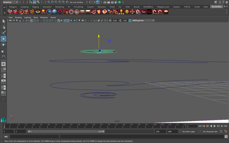
I know it looks weird right now, but that’s okay. Once they’re polygons, we can connect the pieces. As you’ve probably been guessing, we’re going to loft curves again. For this, we’ll only focus on modeling one half of the scroll, and then we’ll mirror geometry in the end. So for that, duplicate the inner curve and the outer curve, but place the inner curve farther above (on the top) and below (on the bottom) of the outer curve since we want the curly part of the scroll to be “extruded” out of the flat part of the scroll. This is what I mean
Once you’re happy with the thickness (which can be changed later as well), loft the curves. The loft options used should be the same as the ones you used to model the cello body. This is what lofting both sets of curves would look like
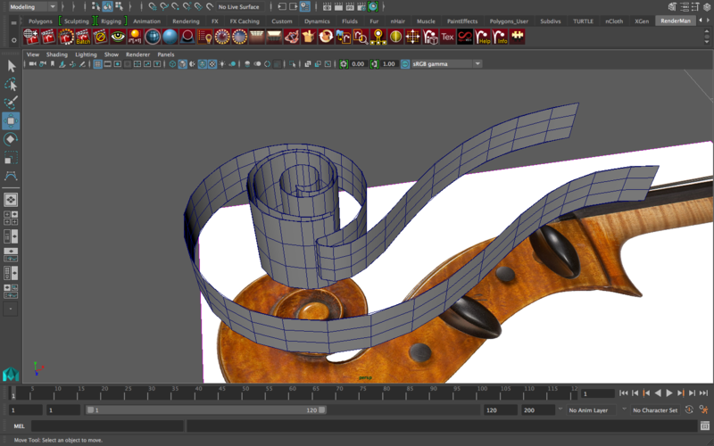
Now you might be starting to get a sense of where this is going. Again, you can adjust the thickness of the scroll here, so I’ll make it a little thicker. Also, when I’m done, I’m going to delete the curves since I don’t need them anymore. You should do the same since they’ll get in the way when you select the edges of the curves.
So we actually don’t need the middle of the inner curve, we just need to see the part of it that’s protruding outside the scroll body, right? So we need to match the top (and bottom, but we won’t do that now since we can just work on the top half and mirror geo later) edge of the outer curve with an edge loop of that same height on the inner curve. So, place an edge loop here
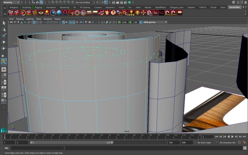
The purpose of that edge loop is to match the height of the upper edge of the outer curve. Once you place that edge loop, delete all the faces underneath it. They won’t be visible in the final model and we don’t need them. So it should look like this
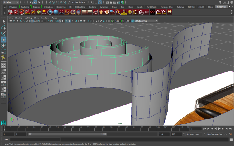
Let’s start filling out the surface/ceiling of the outer curve. To do that, start by using the append to polygon tool near the base of the scroll and work your way upward. First step
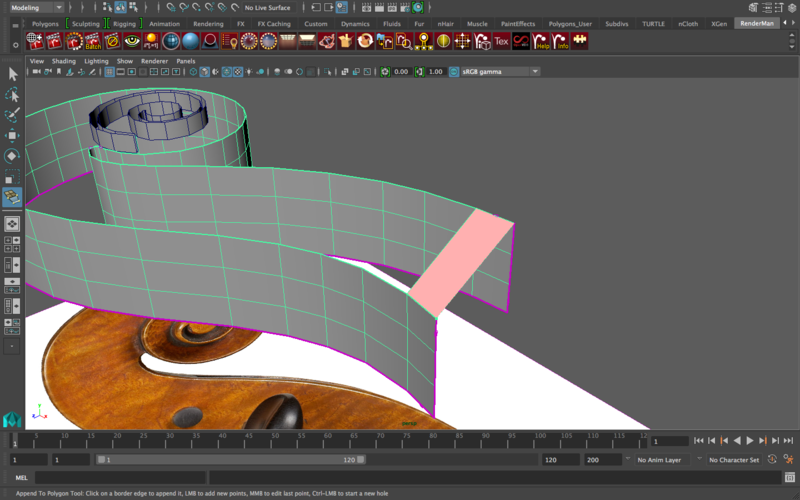
So, you keep going, and then you reach here and things get tricky
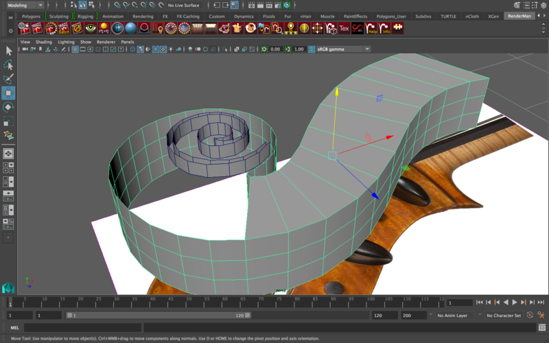
What do we do now? Do NOT continue appending to polygon. The whole point of having these be curves is to reach this stage, and then to incorporate both segments using the append to polygon tool. So, to do that, we need to combine the inner curve and the outer curve (since we can’t use the append to polygon tool on separate objects). Select both objects, go to mesh—>combine, and delete history, freeze transformations, and center the pivot.
Now if you try to append to polygon from the inner curve to the outer curve, it’ll still work, but you’ll see that the face “flips” as you try to connect between the two segments. Why is this? This happens when the direction of the faces of both objects isn’t matching (i.e. you’re connecting the outer side of a face to an inner side of another face—it won’t work). To see the problem as clearly as possible, find the “lighting” button underneath the shelf and click the “two sided lighting” option there. Once you do that, this is probably what you’ll end up seeing
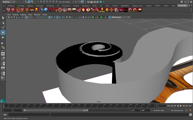
Do you see how these faces turned black? That’s because turning off two-sided lighting makes the “inside” of a face turn black, and keeps the “outside” of a face white. For the scroll body, it makes sense: the outside is white, the inside is black. However, for the inner curve, it’s reversed: the outer faces are black and the inner faces are white, that’s why appending to polygon between the inner and outer curves will not work. So what we need to do is reverse the normals of the inner curve. To do that, select all the faces of the inner curve, and go to Mesh Display—>Reverse. Now, the white faces should be on the outside of the inner curve and the black faces on the inside. Now the append to polygon is going to work.
Before we continue appending to polygon, notice how there’s something obviously problematic about the inner curve and the outer curve: the outer curve is made up of one layer of faces, while the inner curve is made up of two layers of faces. How are we going to combine these two segments without ending up with overlapping faces/triangles? Let’s start by connecting the outside layer of the inner curve with the outer curve’s body. Here is, coincidentally, a good match between nearby vertices. So let’s merge these
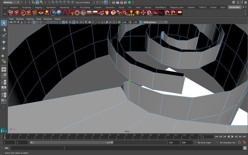
Good, now the two segments are connected by at least one vertex. Unfortunately, the edges right by that area don’t quite line up on the two segments, so let’s make them line up by adding edge loops on the inner curve segment where there are edges on the outer curve segment so we can merge the vertices. This is where I’m placing these edges
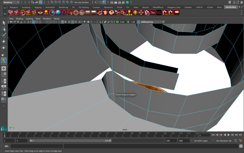
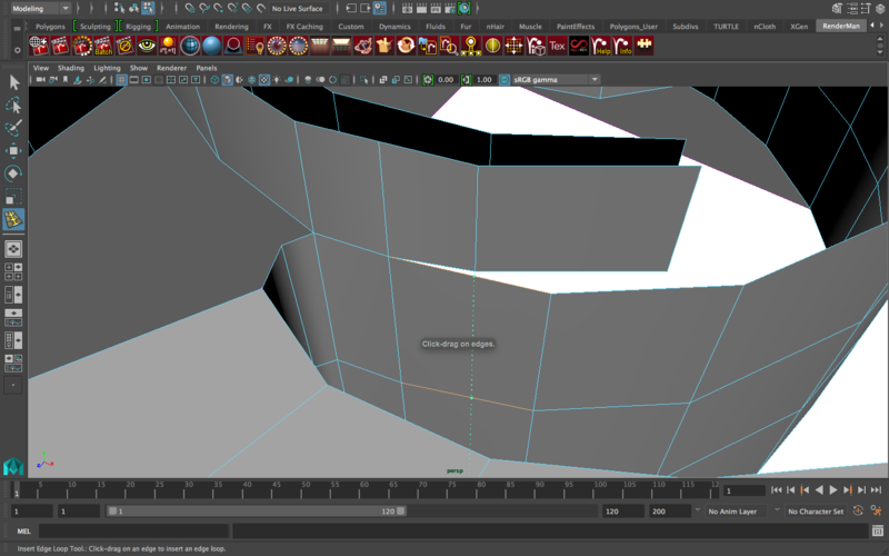
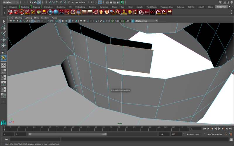
And then connect the vertices, now that they match up. The trickiest part, however, is that final hanging vertex: should we add an edge loop? Probably not (and this will make more sense later), but the reason behind this is that we don’t want to overly emphasize the protrusion of this area from the rest of the scroll. If you look at the scroll image, you’ll see that the curve gradually protrudes from the scroll, not suddenly. So for that we’re going to manually create a gradient, but we’ll do this later. For now, drag the vertex to the next edge and merge them like this
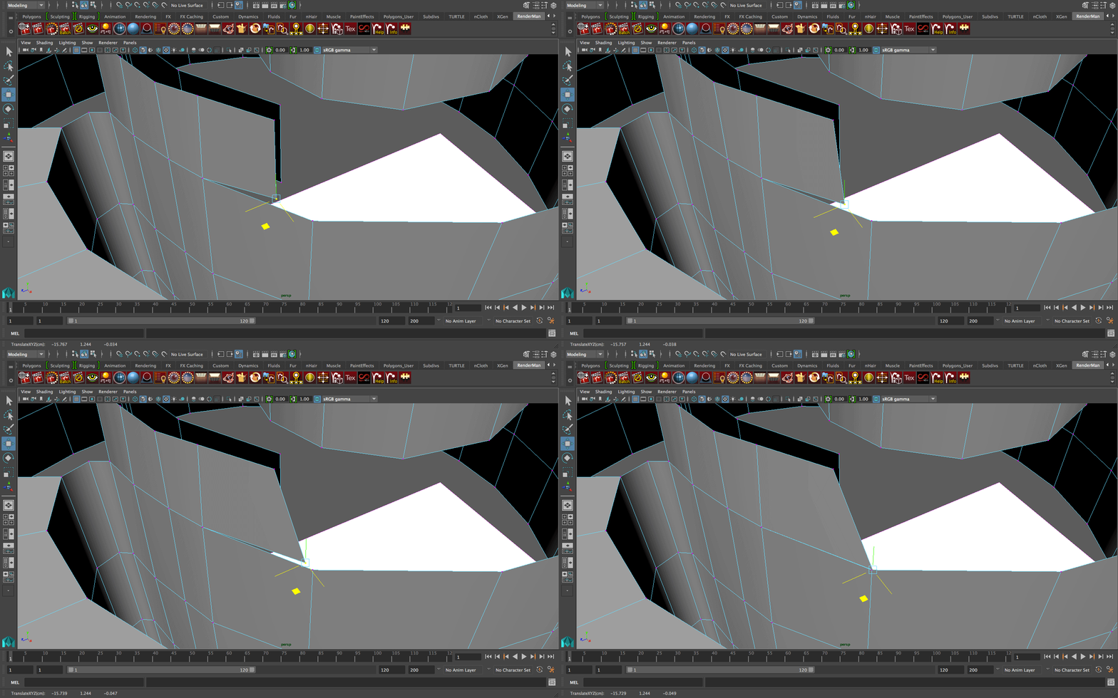
This concept is interesting: remember the edge loops I just added two steps ago? The primary purpose of them was to connect the faces between the inner curve and the outer curve, but I don’t need them there for reinforcing any of the angles, in fact because they’re so close together, they’ll probably create wrinkles when I smooth the object. So I’m going to go ahead and delete the edge loops I made two steps ago (and their vertices of course). The interesting concept to note is that in an example like this, you place edge loops to line up the edge flow to connect segments. Once the segments are connected, deleting the edge loops isn’t going to disconnect the objects, so feel free to delete any excessive edge loops after connecting the segments. It’s like the scaffolding used in construction: you need it for construction, but once construction is over, you don’t need it anymore.
Let’s fill in the top of the inner curve (the “ceiling” of it) by appending to polygon and going around it. Make sure to not create triangles! Every face should have four sides, not 3 or 5 (or more). You should end up with something that looks like this
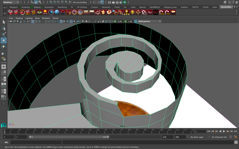
Now that the inner curve is developed to a point where we kind of understand what the final look of it will be, let’s go back to the outer curve and continue appending to polygon along the scroll body.
One problem that I had that you may or may not have is that at some point, making 4 sided faces involved too much stretching, kind of like this
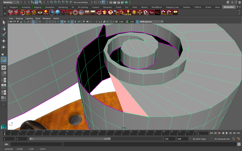
The problem with this is that the next few faces will actually overlap since the stretch is too much, and I don’t want to connect it to more edges because then the faces will have 5 or more sides. So, how do we fix this?
We’re going to delete several edge loops from the outer curve segment so that the edge count of the inner curve and the outer curve is at least closer. These are the edges I’m going to delete
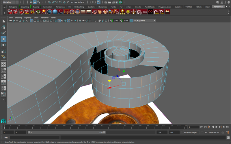
After these are deleted, go back to appending to polygon. Look at how much less the faces are stretching now
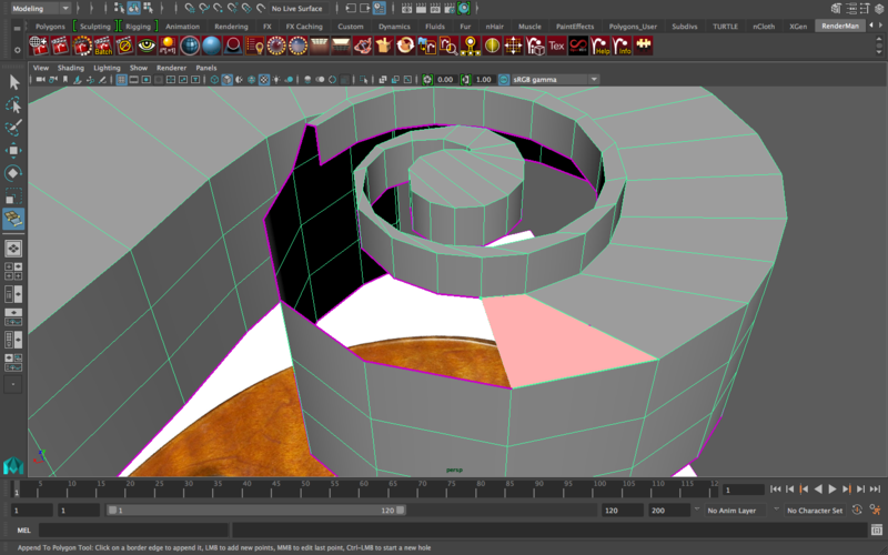
Work your way up to the point where you meet the other layer of the inner curve. How are we going to blend this together with the appending that we’ve been doing? One strategy is to add an edge loop so that the vertex of the inner layer has another vertex to merge to, like this
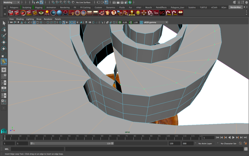
Now merge the vertices and keep going around the scroll, appending to polygons, making sure that every face is 4 sided. You should end up with something that looks similar to this
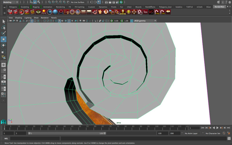
Okay, almost there! There’s a few obvious problems though. The first we’re going to tackle is the fact that the inner curve is protruding so abruptly from the outer curve. So let’s manually move the edges of that first part of the inner curve down so that it’s a gradual slope. It should kind of look like this
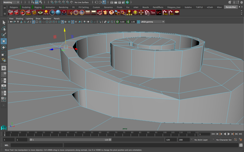
Now it’s a much smoother gradient, which looks a lot better than it did before. If you smooth the object now, hopefully the entire concept behind modeling with curves will click: the shapes are too smooth to attempt using box modeling, and too curvy to use contour modeling for, so for that we use curves. There’s still a few adjustments to be made, however. I don’t like how thin the extruded part of the inner curve is, so I’m going to grab the lower edges and resize them inward like this
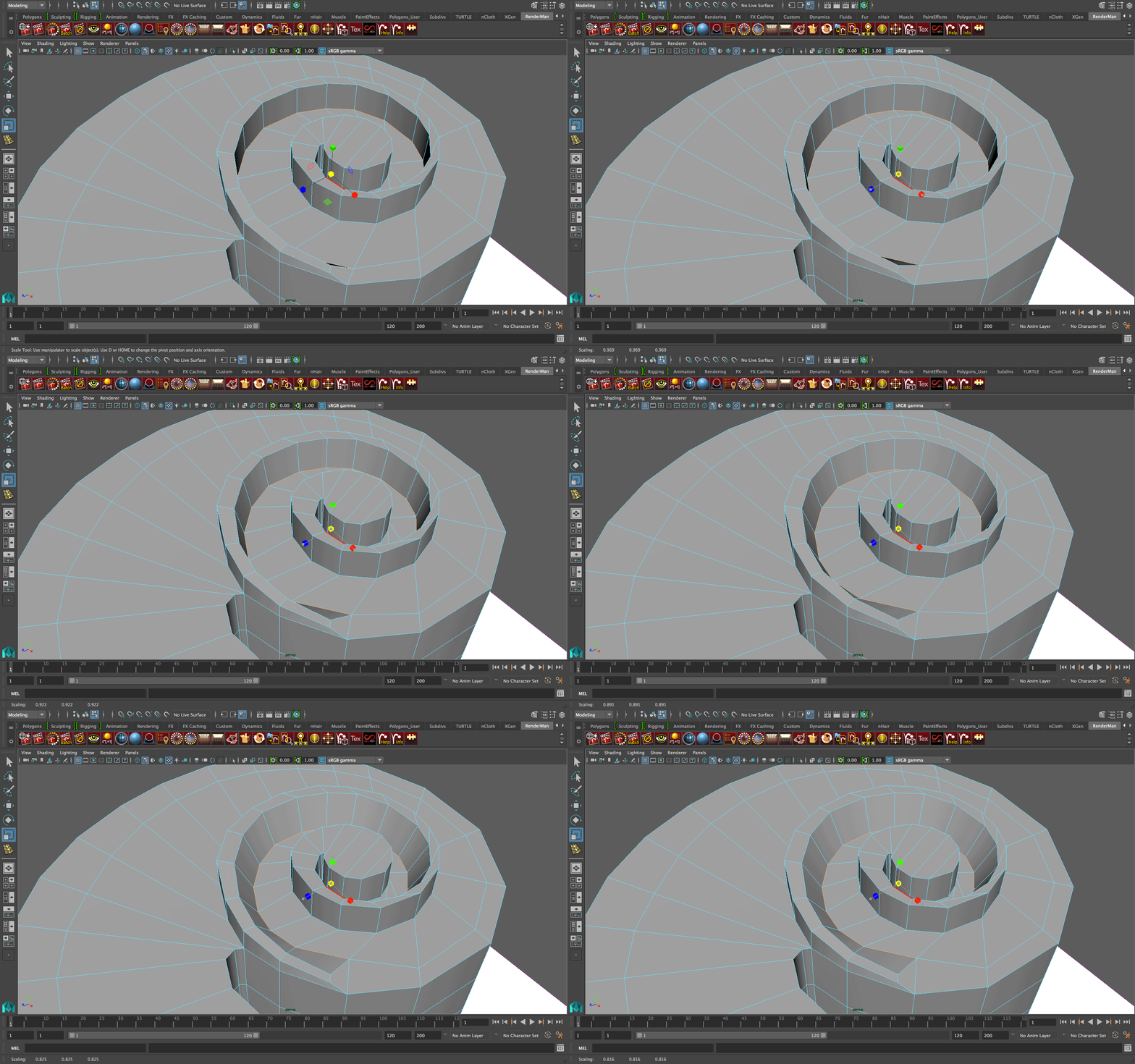
Make any other edits you like. If the curve you made initially wasn’t very smooth, manually move around edges and vertices to smooth things out. If there are wrinkles, delete a few edge loops near the wrinkle and that could help. Personally, one thing I’d like to emphasize is the angle near the top of the inner curve, so I’m going to add a few edge loops where needed. This part is up to you though, and since every curve is different, I’m going to leave this part open ended.
Once you’re done with that, delete the lower half of the scroll (and if the scroll isn’t split in two, place an edge loop that runs through the middle, and delete the lower half). Then mirror geometry downward (negative y axis) and connect the vertices.
Now if you take a look at any cello scroll, you’ll see that the inside of it mostly hollow. So we’ll need to do that for the scroll. Here are the faces to extrude iN
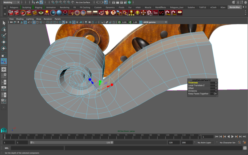
Result -
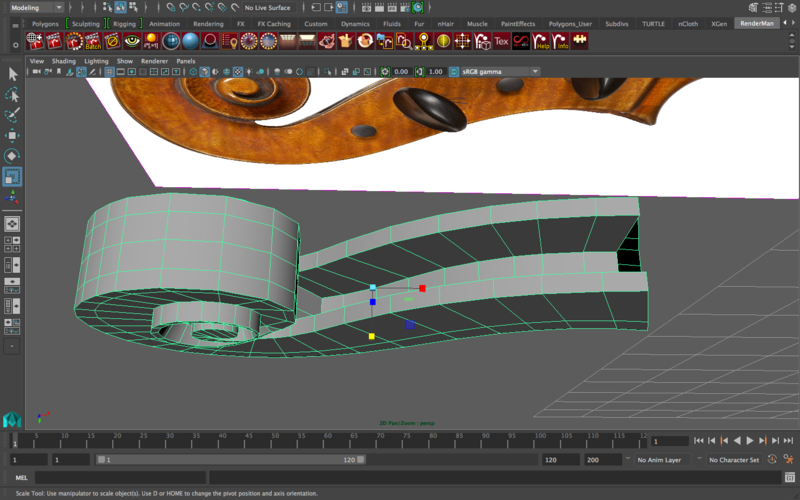
For now, we are done with the scroll! Take a deep breath, the hardest part is over!
CONNECTING THE SCROLL TO THE FINGERBOARD
So I assume that you’ve been modeling the scroll with everything else hidden (I also did it that way). Now, in order to connect the scroll to the fingerboard, we’re going to need to use the reference image, so you’ll need to unhide that if it was hidden. Now, match the reference image of the scroll to the reference image of the side of the cello.
Now, extrude the end of the fingerboard and, following the reference, push it closer to the base of the scroll
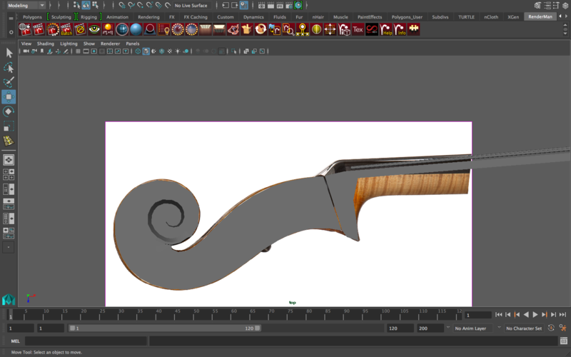
All I did for the image above was just extrude the end of the fingerboard several times and match it to the background reference image. The plan is to then connect the corners (vertices) and delete any double faces. However, there is a problem:
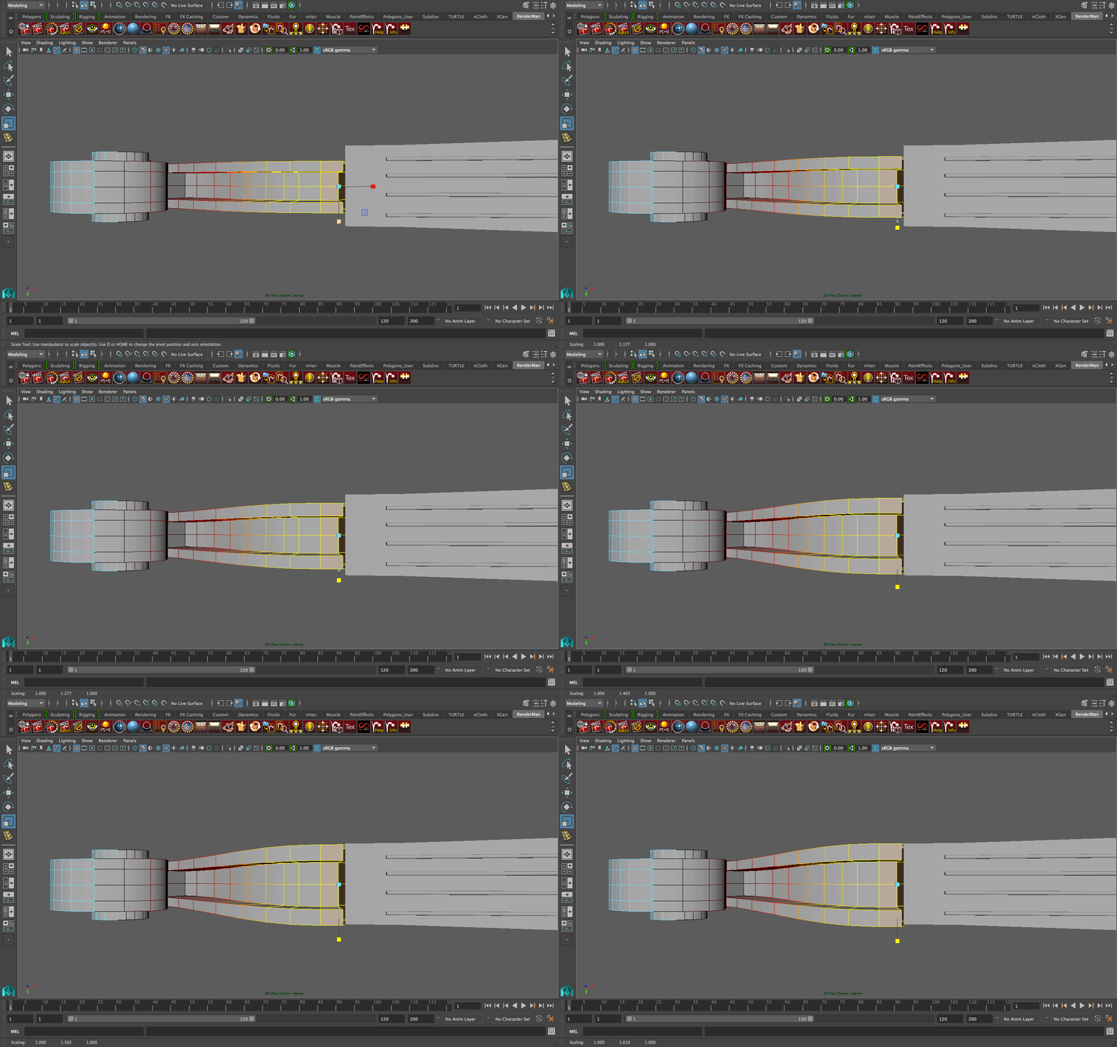
When I looked around the base of the scroll, I found that there’s a thickness discrepancy between the base of the scroll and the end of the fingerboard. This is actually a good thing, because when we fix the size of the scroll, it’s going to look even more realistic. To fix this, I’m going to select the faces at the base of the scroll, and then I’m going to use soft selection (click “b”) and I’ll resize it. This is the result
If you look up “cello scroll” on google images, you’ll find that the majority of the designs actually involve this sort of gradual width extension as you go down the scroll, so I’m glad the discrepancy happened. Now we’re ready to merge vertices as needed between the scroll and the fingerboard.
Final step: grab the ends of the strings, extrude them, and stretch them all the way to the back of the scroll. Naturally, the strings’ spacing might be too wide for the scroll, so in that case move them closer so that they fit within the width of the scroll. The final result should look something close to this
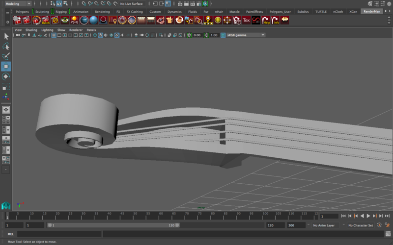
You’re done with the scroll!!
MODELING THE F-HOLES
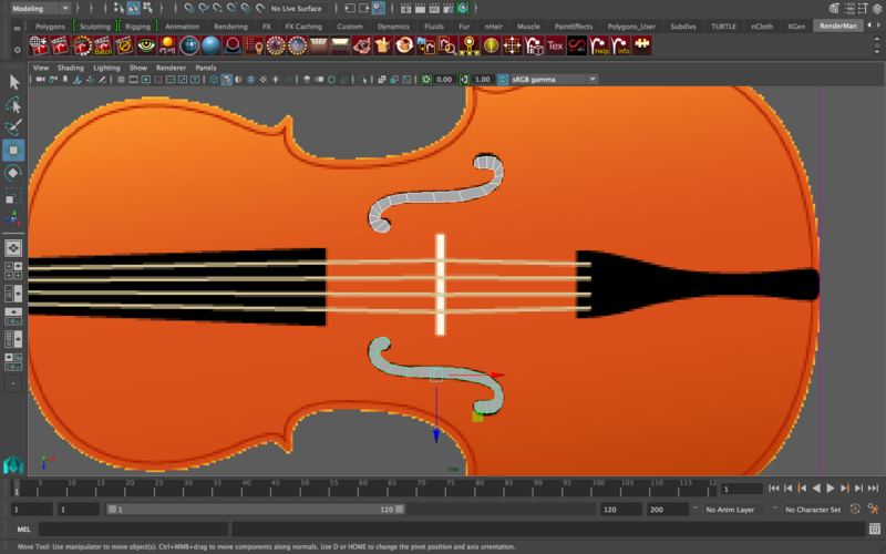
NOTE: The F-Holes are called holes for a reason: they are actual holes in the cello. It would take a lot of effort to actually carve these holes into the cello (you’d need to use booleans and alter the edge flow accordingly, which will create all sorts of wrinkles around the cello.) What’s stopping me from going this route isn’t because I don’t want to do the effort, it’s because I can get the same final look using a much easier way
In general, when you shade/texture a material 100% black (i.e. the slider is all the way toward the black side), it actually looks like a hole. No light bounces off of it (you’d need to change ambient color). So actually if you’re texturing an object black, you wouldn’t want to push the slider all the way toward black (or white for that matter), you’d only want to get it close, but not completely all the way. We’re going to exploit this situation to make the modeling of the F-Holes easier (yay for hacking).
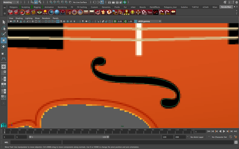
Like other objects with that much curvature, let’s use CV curves. Trace the f-hole with a cv curve, go all the way around (if I’m going all the way around I usually leave a space between the start point and end point, and then when it becomes a poly I’ll just append to polygon to connect that gap). For me, the curve looks like this
Duplicate the curve, but since this should be really thin, only move it up slightly
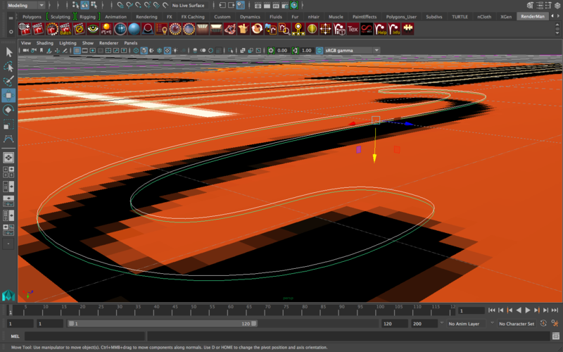
Loft the curves. Then, append to polygon the gap that you left between the start point and end point. Then, when you’re done, select the entire lowest edge (outline all around the hole), and go to mesh—>fill hole. It’s the same process again: use the multi-cut tool to connect the sides.
When you’re done with that, place an edge loop exactly through the middle of the side of the f-hole, so that you can delete the upper half (or the one you did not work on) and just mirror geometry. Then connect the vertices. It’s the same exact process as the curve modeling we’ve done before this.
When you’re done with one f-hole, just mirror geometry the entire object to the other side depending on which axes you’re using in your scene, and place the other hole where it belongs, using the reference image for guidance.
This what the final thing looks like for me
MODELING THE FINAL COMPONENTS
You’re almost there! Hang in there!
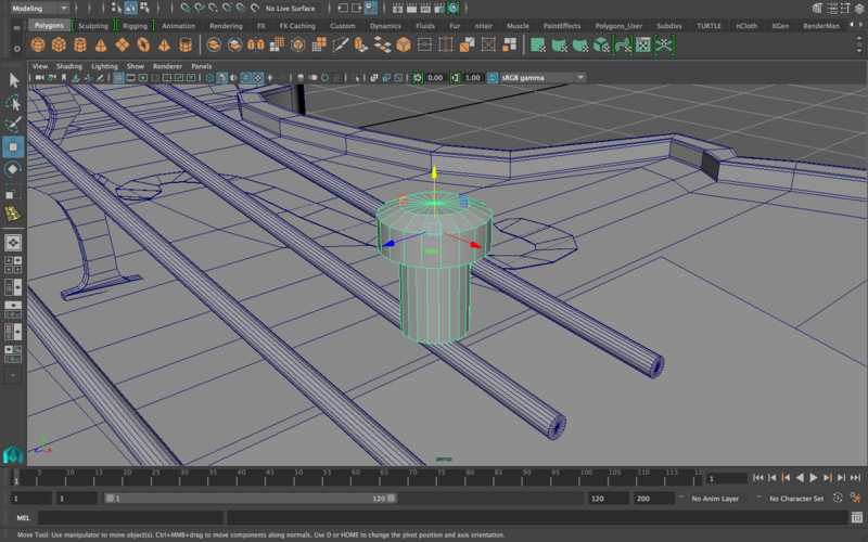
Let’s model the Fine Tuners:
These essentially look like nails, so we can get away with really simple modeling and it’ll still look pretty accurate.
Start with a cylinder. Grab the bottom side of it, extrude and resize down, and then extrude again and move it down so that it looks like a nail.
Grab the top side, extrude and resize down and move up without extruding again so that it kind of looks a little rounded (not too rounded though).
The final tuner should look like this
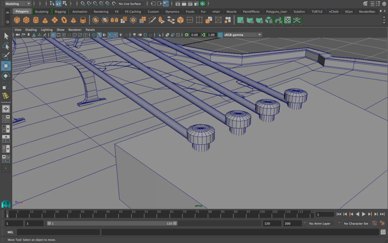
Duplicate that four times and place each one on top of the base of the strings at the end of the tailpiece, like this
Now let’s model the Tuning Pegs for the scroll:
Take a look at this image for reference. This is a tuning peg (there’s many varieties of shapes, but let’s go with this one)
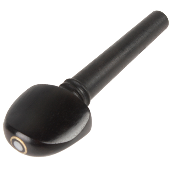
Based on this reference, I’ll start with a cube for the flatter part of the peg, and then I’ll attach a cylinder for the peg’s connection to the scroll. This is what I’m starting with
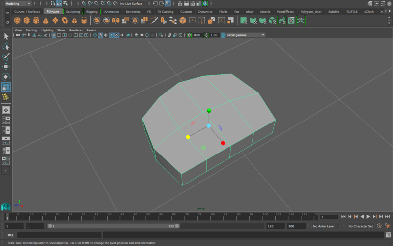
I’ll smooth out the shape to get it to look closer to the peg. Also, when I attach the cylinder (and have several extrusions on the cylinder to make it look like the image) it should look something like this
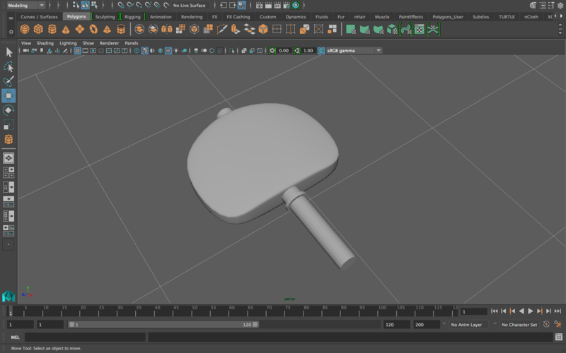
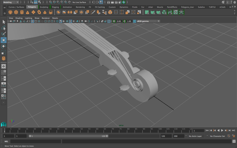
Then, placed on the scroll, they’d look something like this (you can combine them or parent the cylinder to the handle—it’s up to you)
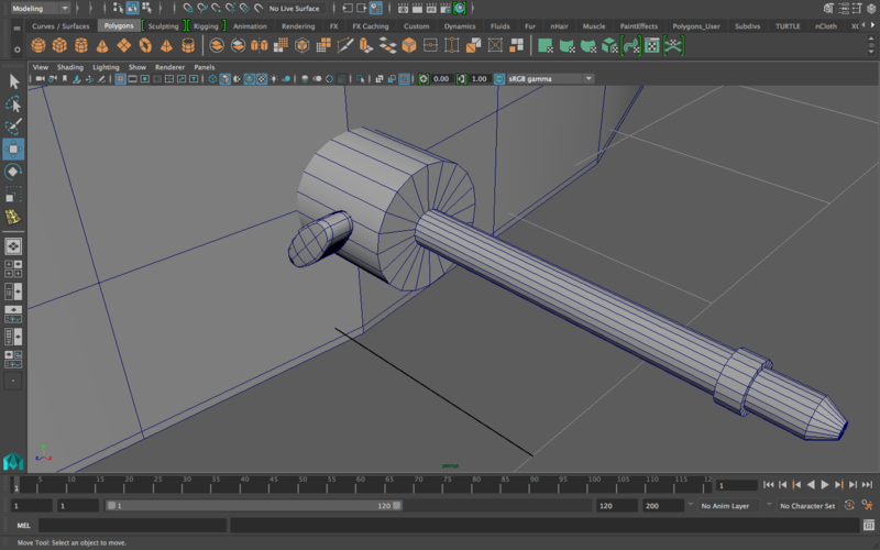
Let’s model the Endpin:
Take a look at this image. We’ll use this for reference
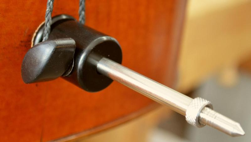
So this should be a simple model. The plan: a cylinder for the base of the endpin, and then I’ll extrude that end to a smaller radius (the radius of the silver part) and then I’ll extrude that out. Then I’ll extrude near the end, make it smaller, and pull it out to get that tip to look like the tip of a pen. For the lever by the side, I’ll start with a cube and alter the position of the edges to make it look more oblong like this. Here’s what the final model should look like
FINAL NOTE
There’s only a few things I’d like to tweak: I’d like to make the cello body thicker, so I’m just going to select that part, resize up, and make sure that it’s not overlapping anything.
Now the rest is up to you: what do you like and what do you not like? Edit anything as you find appropriate. There are parts I skipped out on for the sake of convenience, since they’d involve more of the same techniques (i.e. the string going around the endpin, extruding the front of the fingerboard to separate it from the cello body). Hopefully that shouldn’t result in a much lesser model. Also, I wanted to provide you with the space needed to add your own touches and change the model however you like, so there are parts of this tutorial that I covered extensively and flooded with screenshots, and other areas where I just showed the starting point and end point, giving you room to apply the concepts you’re seeing instead of just blindly following what I have here.
For the sake of display, it’s generally a good idea to NOT combine all the segments together into one object. Just select everything and parent it under the cello body. Then you can move and resize the whole object as you need.
Interesting thing to note: many other string instruments in the same family (violin, viola, double bass) pretty much have the same shape, with few tweaks here and there. So you can actually take this model and turn it into any one of these models pretty easily. Keeping things uncombined helps achieve this if this is something you’d like to do.
You’re done!! Pat yourself on the back! This was a difficult, time-consuming lab with many, many steps. I can promise you this though: you should now feel comfortable modeling pretty much any hard-surface object. This tutorial involved so many concepts from general approach (i.e. contour modeling, box modeling, curve modeling) to important smaller points (i.e. interaction between normals and the appending to polygon tool).
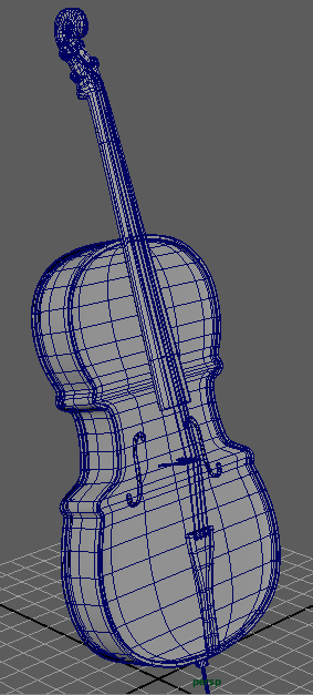
Here’s the final model (wireframe on shaded)
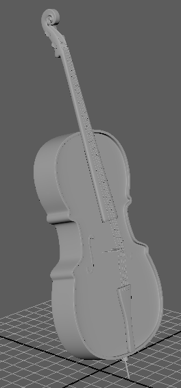
And here’s what it looks like just shaded, without the wireframe
Remember to submit your model onto bcourses! Now take a well deserved break!!