Warning
The Modeling 2 lab is considered one of the toughest labs to complete in UCBUGG. If you feel stuck at any point in the lab, please make a post in the #help-questions channel on Discord.
HANDY TOOLS
Before we begin modeling, lets review some helpful tools/hotkeys that you might find useful in this lab.
Infinite Undos
The default setting for undo in Maya is 50 undos which is not nearly enough. If you have not already done so, make sure to turn on INFINITE UNDOS NOW!
Click Windows -> Settings/Preferences -> Preferences.
On the left, there’s a window of Categories. Under Settings, find Undo and change your Queue setting to Infinite
Snapping While Transforming
You should be familiar with the three transformations (translation a.k.a. move, scale, rotate). Snapping refers to transforming in other increments (such as moving by 1 or rotating by 90 degrees).
On your menu bar, you should see magnet icons. Those are the different snaps you can choose to have on at all times. The first icon snaps to grids, then snaps to curves, snaps to points, snaps to projected center.
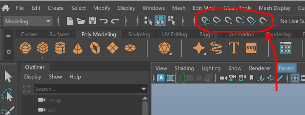
You can also activate these snaps with hotkeys:
| Shortcut | Tool |
|---|---|
| Hold X | Snap to grid when translating |
| Hold V | Snap to vertex when translating |
| Hold J | Snap tool for move, rotate, scale |
OPTIONAL: If you attempt to snap multiple components (vertices, edges, faces) along
the same area, such as the grid, it will retain the same spacing between each component.
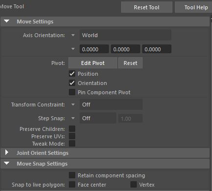
You can disable this behavior by opening the Move tool’s settings (Windows → General Editors → Tool Settings then use the Move Tool) and under Move Snap Settings, disable Retain component spacing.
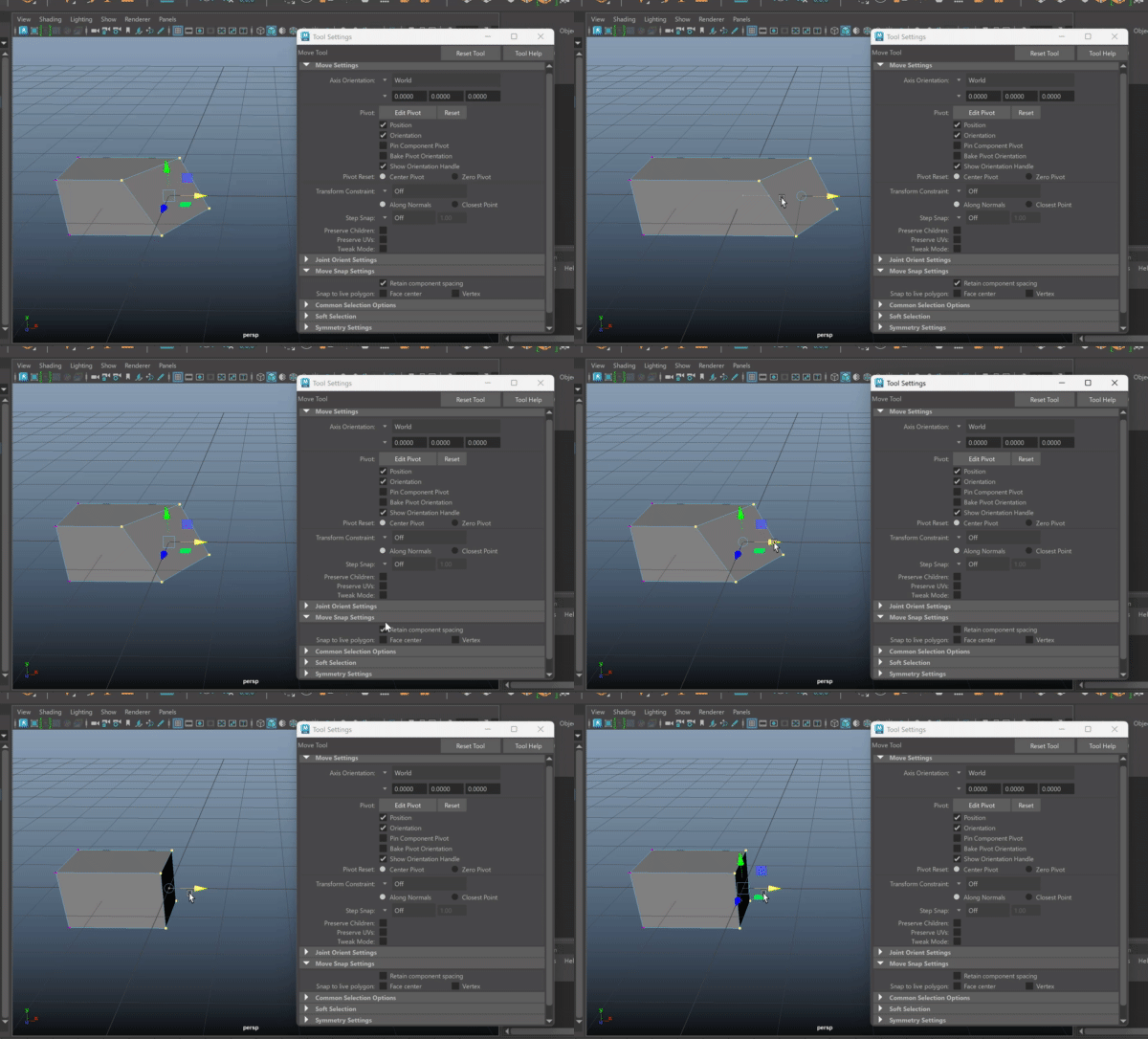
The difference in keeping Retain component spacing on and off is shown below. Notice how the vertices all snap to the grid when it is disabled:
Other Tools/Shortcuts
Here are some other useful keyboard shortcuts.
| Shortcut | Tool |
|---|---|
| G | Opens last used tool. Useful so you don’t keep trying to find the tool. Only works after using a new tool. |
| Ctrl + Alt + S | Save your file under the original file name + increment. Useful for saving multiple copies/versions of the same file. (Fox.ma, Fox_V2.ma, Fox_latest.ma, etc.) |
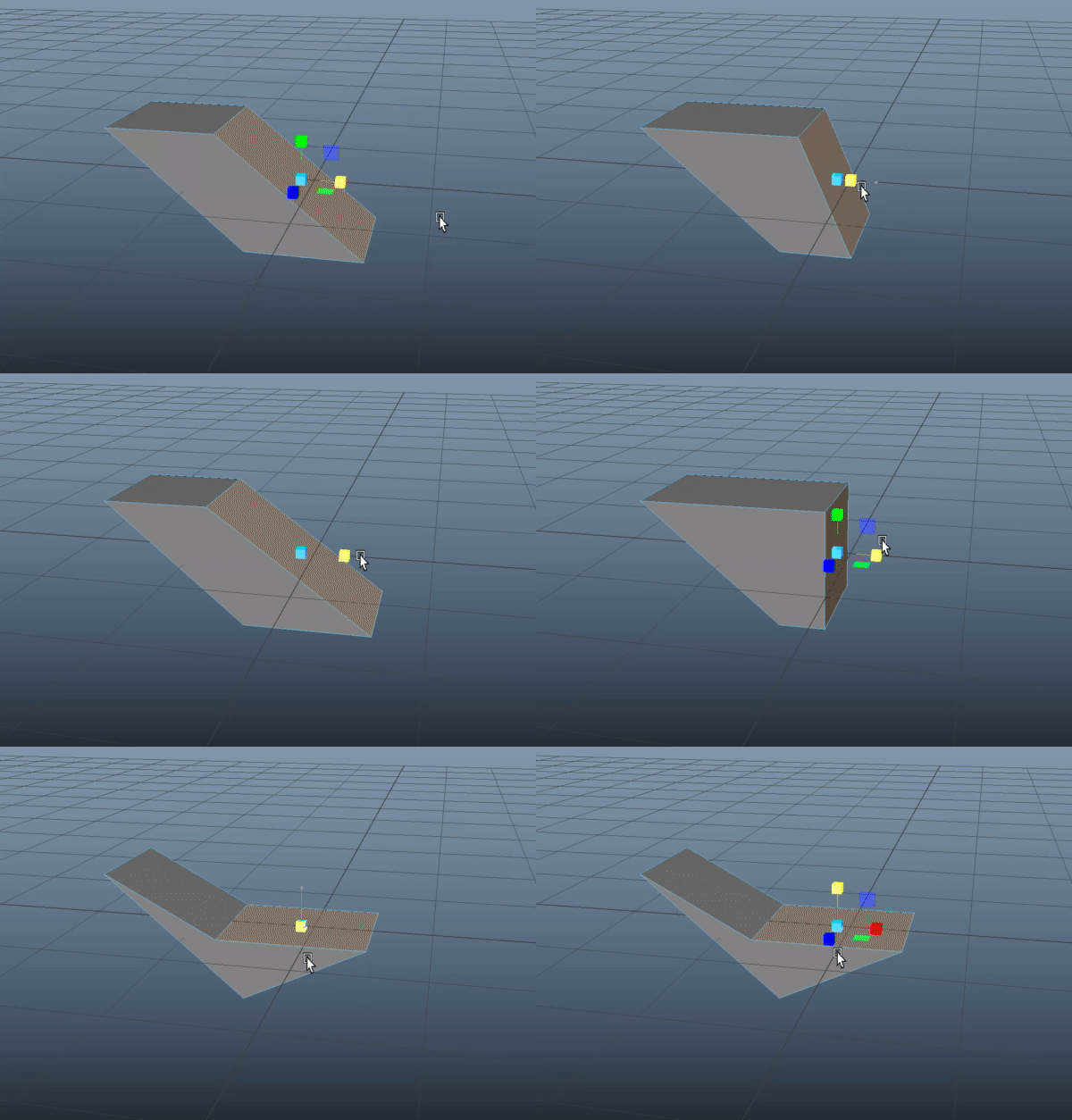
Another useful trick is using the Scale tool (shortcut: R) to flatten/straighten edges/faces.
Now, lets go onto the lab!
ADVANCED MODELING
This week we’ll be modeling a classic UCBUGG fox using different techniques. It’s up to you to use these techniques as you see fit!
(Author’s Note: It ended up looking like a pig so be careful of copying me artistically.)
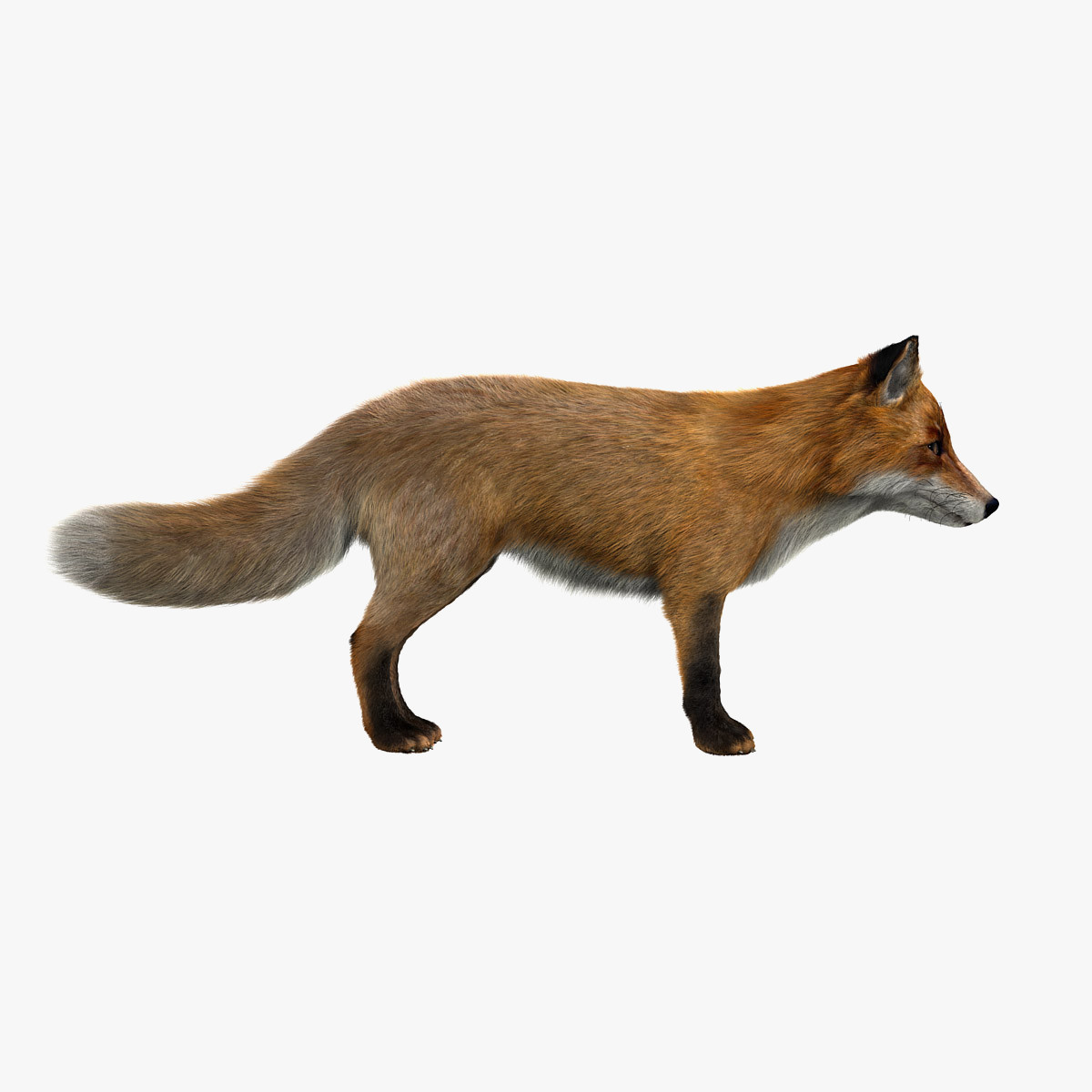
Download this side view of a fox to use as a reference.
When modeling your own assets you’ll be using your character sheets as a reference.
Fox Image: original_fox.jpg
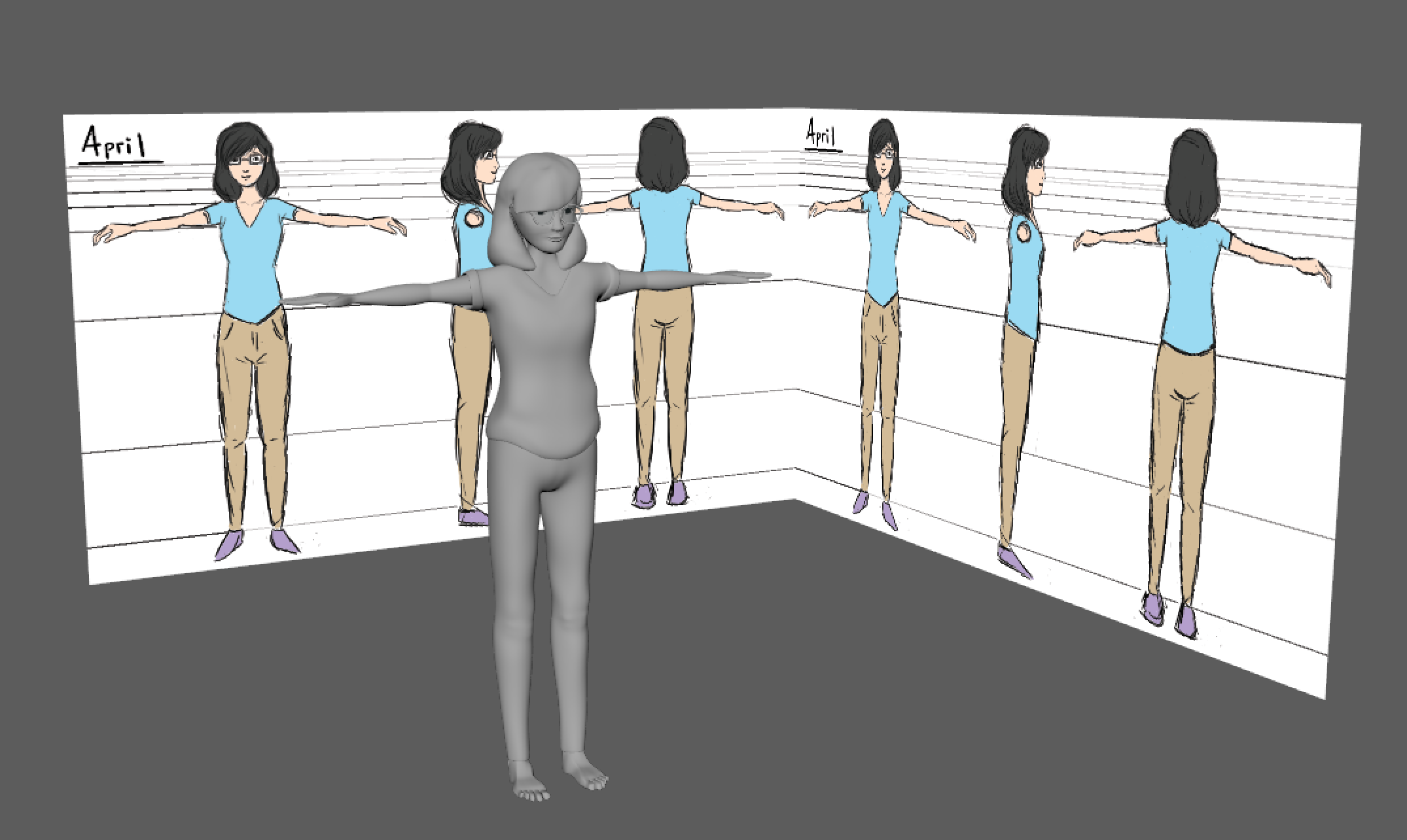
This is an example of how you can use a front and side reference sheet to help model your character. We’ll be doing something similar.
Reference Images
For this lab, we only use a side reference. As such, the front of the fox can often turn out looking weird (like a pig) without something to reference from. You are free to use more references for the fox if you would like.
To bring in your reference image, press spacebar in Maya to get out of Perspective mode and enter side view mode by pressing spacebar again while your cursor is over side view mode.
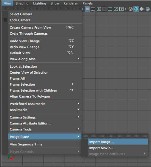
Press View → Image Plane → Import Image and Maya should automatically open up a box to the sourceimages folder of your current project directory. Navigate to wherever you saved the reference image and double click it. If you didn’t go into side view mode, your reference image would have imported at whatever angle the camera was facing which would make the orthogonal views useless.
You should have an image plane with the fox in your scene now. I personally like to translate the fox -20 units on he x axis so that it’s out of the way in perspective mode since I’ll only need it for side view mode. Here’s what my scene looks like now.
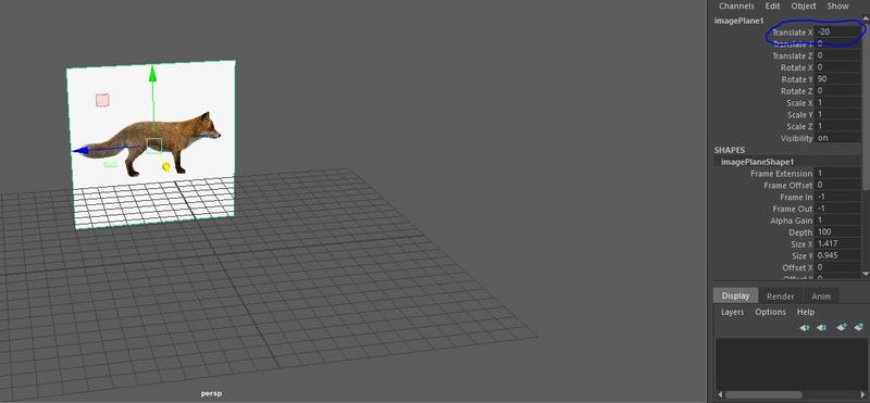
And this point, it would be wise to save initially (if you haven’t already). You will want to make it a regular habit to SAVE YOUR WORK!
Go back to side view mode and we can start box modeling.
Create a cube from the polygon primitives menu.
SIDE NOTE
For the love of all that is good and green on this sweet earth please don’t use any NURBS Primitives when you are modeling. NURBS are a type of object in Maya that will essentially only show up in the viewport. That means anything made from a NURBS primitive will not show up in ANY renders, final images etc. They will become useful later on in the pipeline for rigging, however, for modeling we want to stay away from them!
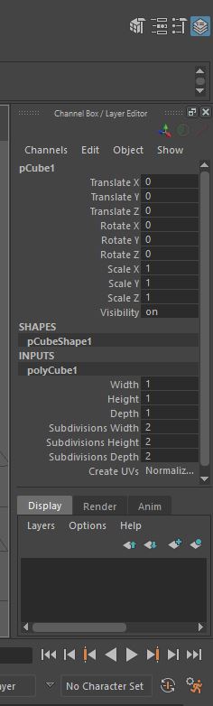
Go into the Channel Box and click Inputs to change the subdivision values to 2 for Subdivisions Width, Subdivisions Height, and Subdivisions Depth.
If you can’t find the channel box, click the blue icon on the top right as seen below. Also, be sure that you have your cube selected.
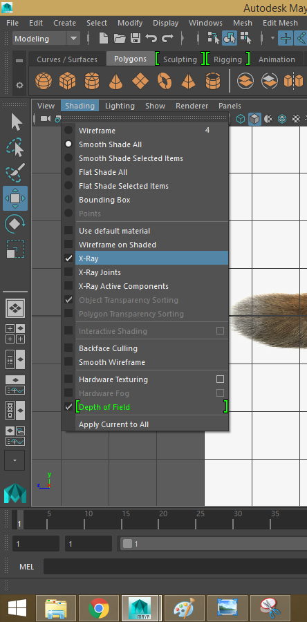
Next, go to Shading → X-Ray. This makes your mesh half transparent so that we can model it while looking at the reference image.
The key to box modeling is to start out very blocky and slowly adding more detail. Don’t be afraid to have an abstract model for the majority of the time. Always have a reason for every edge loop you add. Avoid adding edge loops unless you’re going to move, scale, or rotate it.
STEP 1: TORSO
Start off with fitting your cube into the base of the torso. Notice that my edges end at the armpit and thigh of the legs. As you’re modeling, you want to keep in mind where you place edges along your model. A general good practice to keep good topology or “edge flow” is to place edges near the joints of the fox/thing you are modeling (arms, legs, head, etc.). Keeping good edge flow and placing your edges carefully will become more important when we get into rigging so do your best to keep things clean and organized as you model!
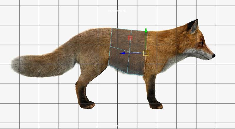
An important note: Although we are using a cube that has depth to it, in side view mode, it’s hard to tell that you have edges/faces on top of each other. In other words, from the side view a cube looks just like a flat rectangle when it actually isn’t.
To avoid the mistake of only selecting one half of the cubes’ edges/face/vertices, use Shift-Click + Drag to select/deselect edges/faces.
Here I selected all the faces that you can see from the side view but also the faces on the other side that you can’t see from this angle.
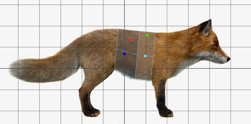
See that I’ve selected all the faces including these front facing ones. However, I want to only extrude these front facing faces, not the side ones.
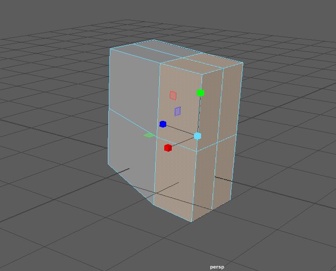
So I Shift-Click + Drag again over the side faces to DESELECT.
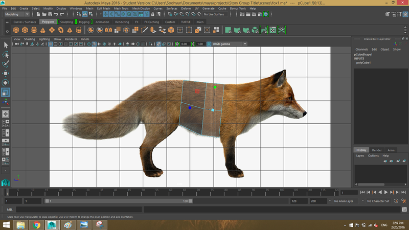
And voila! You can’t tell in this view but if you go back to perspective view, you’ll see the front faces are highlighted. You can also tell by the manipulator in this image. I used the same technique on the edges to fit the cube along the side of the fox.
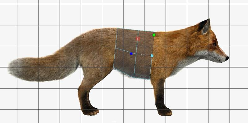
BE SURE TO UNDERSTAND THIS TECHNIQUE BEFORE MOVING ON.
Play around with selecting/deselecting edges and faces around with just the cube and look back and forth between side view and perspective view so that you are doing what you expect to be doing.
The biggest gotcha here is that you might be selecting faces or edges behind what you see without realizing it.
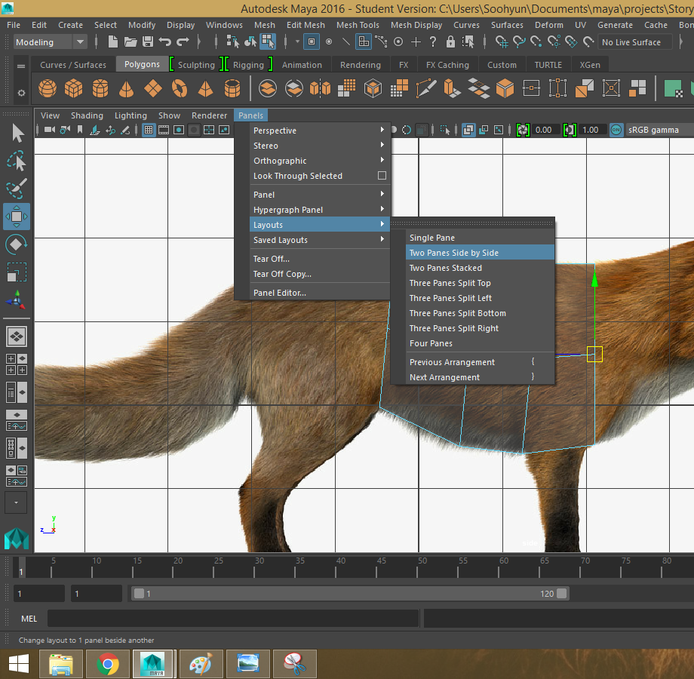
It might be helpful to go into Panels → Layouts → Two Panes Side by Side. This is an easy way to see two views, or your side view and perspective view, at the same time!
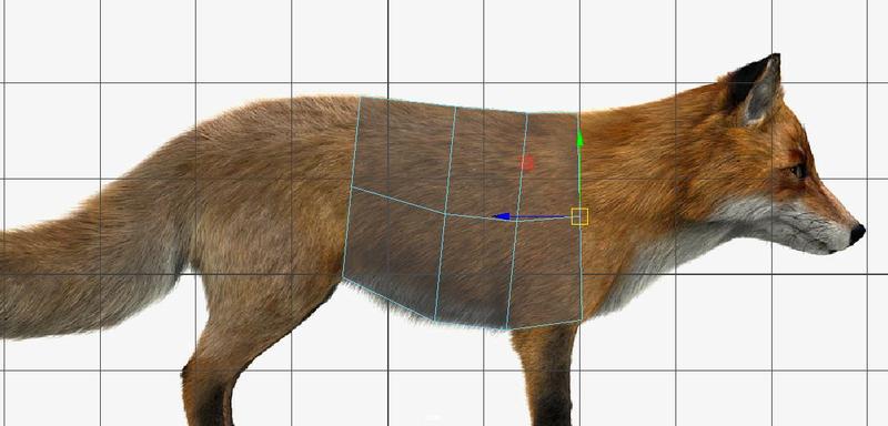
Next, extrude the front faces and pull them to the front of the fox’s arm.
Extrude those same faces again and bring it up to the neck.
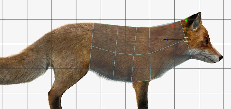
You start to see why having the hotkeys QWER memorized is so useful. While box modeling, you switch between the translate, scale, and rotate tool constantly. In this example, I extruded, moved the faces near the neck, scaled down the faces to fit against the image, and rotated the faces so they fit along the curve of the fox’s anatomy.
Recall from lecture when we talked about good edgeflow. You want to constantly maintain good edgeflow so I fixed mine by adding an edgeloop between the arm and neck which I scaled and moved to fit against the neck. I also moved some spacing on the torso and arm. Now everything looks somewhat evenly spaced and my edges are along the arms, legs, and neck.
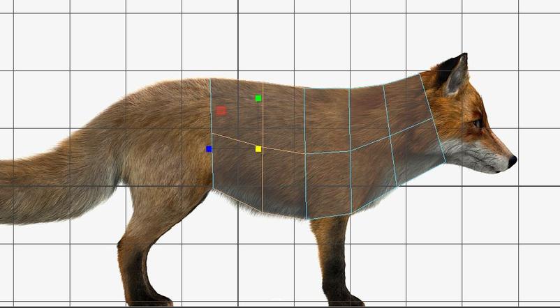
Next, extrude the faces on the back to where you think the rump of the fox will end. The edgeflow here is unbroken but it’s still rough near the butt of the fox.
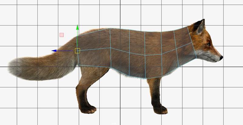
I added an edge loop to make it smoother.
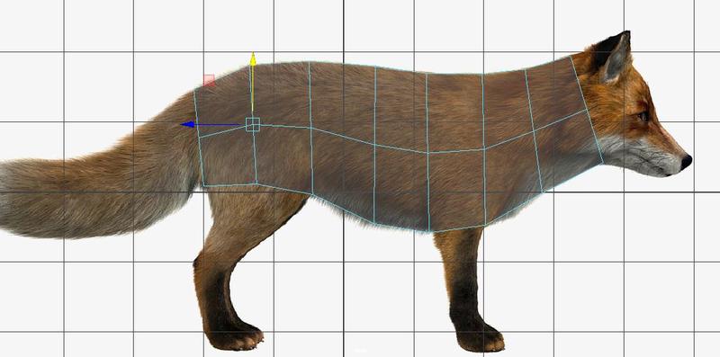
Once you’re satisfied with the torso, let’s Delete History. Then save this fox1.ma scene.
For good practice, let’s click Save As and create a foxLatest.ma file, then a fox2.ma file.
We’ll be working in fox2.ma from now on and have a backup called fox1.ma and your group members would be using foxLatest.ma.
STEP 2: FRONT LEG (Extrusion method)
There are two ways to model limbs in general. You can either extrude off of the main mesh or create a separate object that you later “stitch” vertices to. It’s up to you which method you want to use as I’ll be showing you both methods with the legs.
Also, don’t worry about modeling all four legs! We’ll be making one front leg and one back leg, then copy it over to the other side.
Find the face closest to the front leg and extrude it outwards.
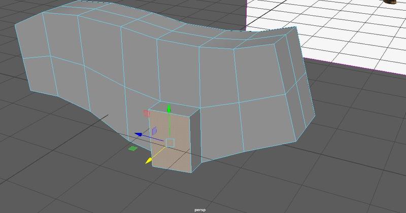
Then extrude the bottom face of the “shoulder” and use the side view to check out long it should be.
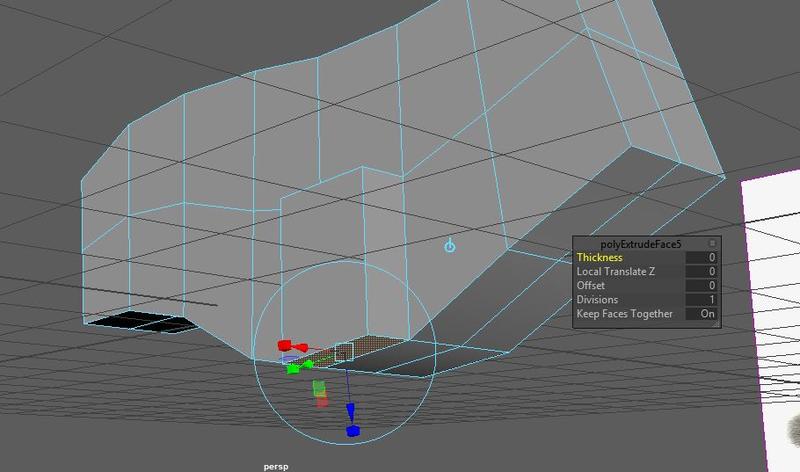
Once again I want to add edge loops down the leg to even out the spacing. Notice that I added in another edge loop where the arm is bony from the knuckles. I may want to add more edge loops in the future but remember, we want to keep things blocky and abstract for now before adding details.
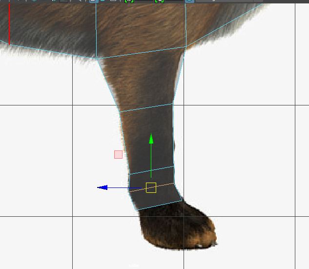
I extruded more faces, tweaked my edges, and got this.
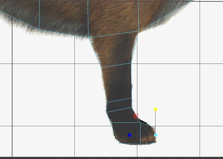
Something to keep in mind when modeling is whether you’re going to smooth your mesh or not. Often times, when modeling, I’ll extrude muscular areas farther out than the reference sheet says. This is because when I smooth, it’ll smooth down to where the muscle should end.
Here’s a screenshot of my front leg smoothed out. I’ve lost a lot of the sharp bony edges of the foot so I’m going to want to add in more details and edge loops to achieve that bony look. But again, I’ll worry about details later.
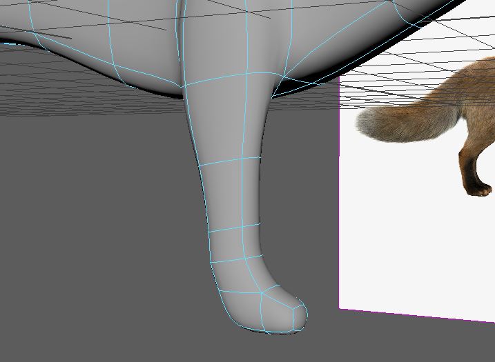
STEP 3: BACK LEG (Stitching Method)
The stitching method works by merging vertices together. This means, the number of vertices on the area you’re going to stitch onto MUST EQUAL the number of vertices of the area that is being stitched into the main mesh.
Note that I have 6 vertices where the back leg mesh will fit in.
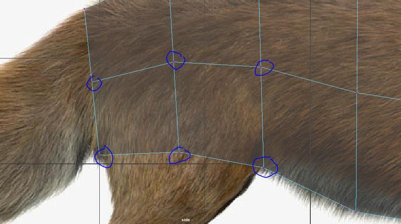
Create a cube. Go into the Channel Box → Inputs and set Subdivisions Depth to 2. This should give you a cube like the image below with 6 vertices on one side. I moved the cube out of the way of the original mesh like so.
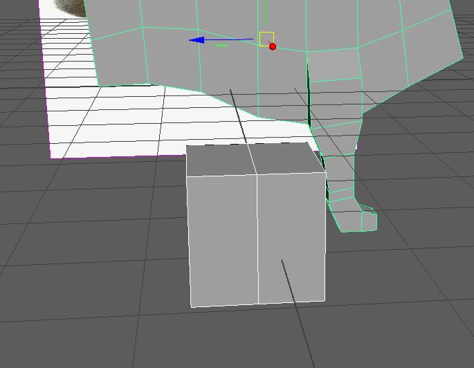
In side view, move your cube so that it fits along the face where the back leg should begin. Eyeball where the vertices should go and adjust accordingly.
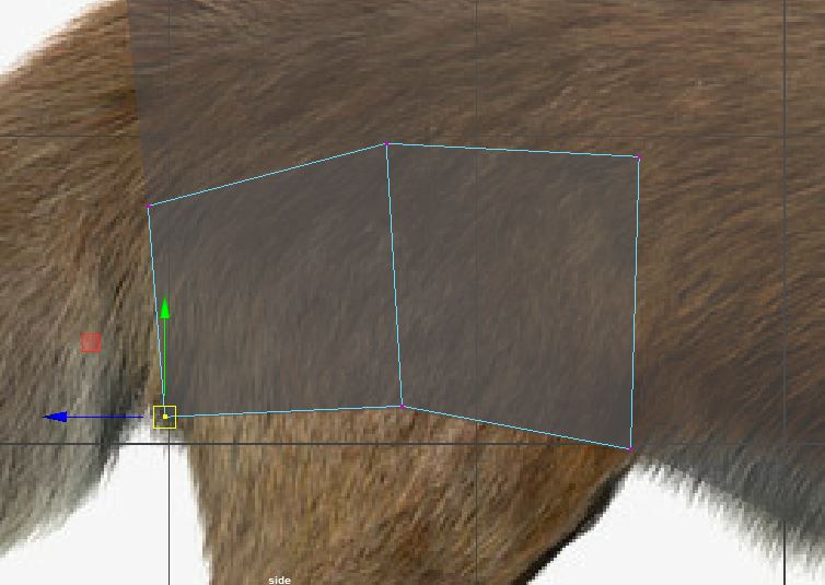
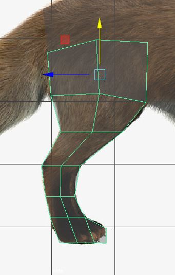
Like we did with the front leg, extrude faces, add edge loops, and adjust to maintain good edgeflow. I went ahead and got this.
Let’s Delete History on BOTH our objects just in case.
Then, go into Face Mode, and delete the faces that will be facing each other when stitching on both objects.
This is important to remember: if you were to merge/stitch the vertices together without deleting the faces on both objects first, you would end up with two faces on top of each other which will lead to bad topology and “manifold geometry”. We definitely want to avoid that!
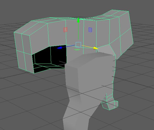
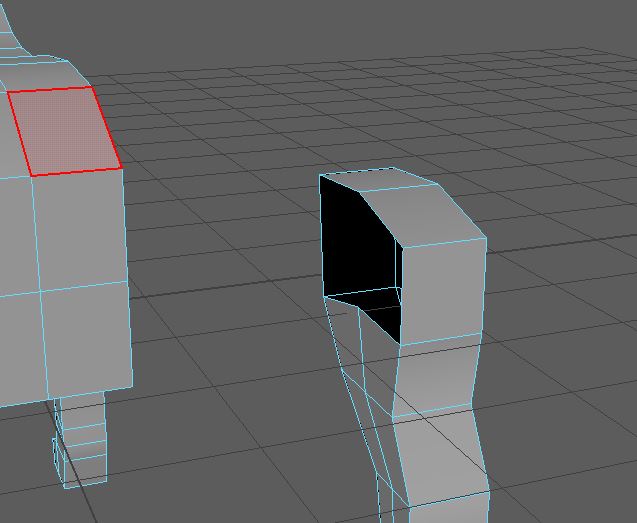
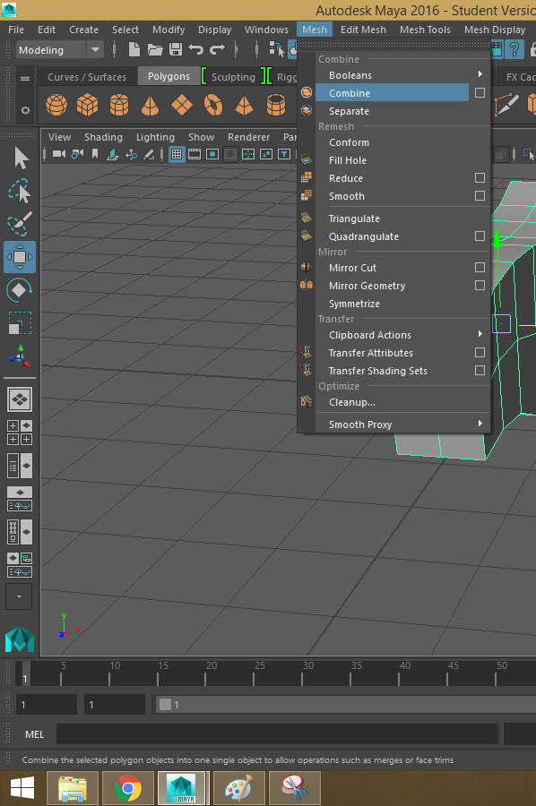
Bring in your back leg object as close as possible to the fox mesh. Leave some space so that you can easily see which vertices match with each other. Select both objects, then click Mesh → Combine.
In order to merge vertices, Maya needs to consider the two objects as one.
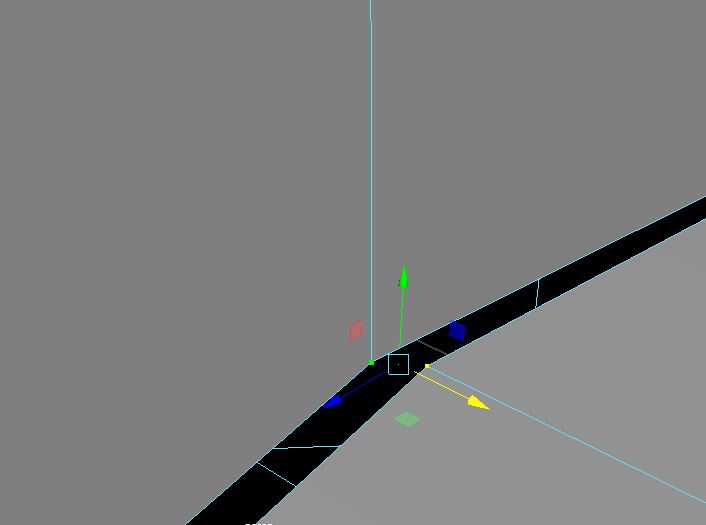
Go into Vertex mode and highlight the two vertices that you want merged together.
Click Edit Mesh -> Merge to center.
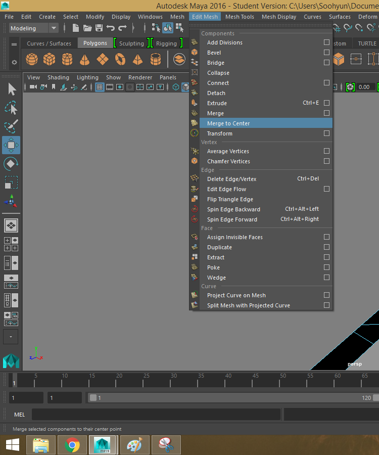
The vertices will snap to the space between them and become one. Do this for all 6 pairs of vertices and make sure your mesh is SEALED. When you’re done stitching vertices make sure you don’t have any gaps, otherwise, your skinning will be ruined.
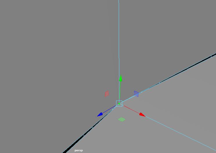
A good way to check if you have properly “stitched” the leg on, is to go the Shelf and click on the Sculpting tab. In the sculpting menu, you want to select the Grab Tool on the shelf (4th tool from the left).

If Maya lets you sculpt on your fox mesh, that means that everything is good to go! If you get a red message at the bottom saying “Sculpting cannot be performed on manifold geometry”, that means there is a problem with your fox’s topology. It’s probably a good idea to fix it now before moving on (ask a facilitator for help if you need!).
This is what your mesh should look like so far. I’ve made some edits to the width of the back leg and moved edges around so that the transition to legs is a lot smoother.
If I had a front plane reference image, I would use it to determine the width of the body and legs but for now, I’m just going to eyeball it.
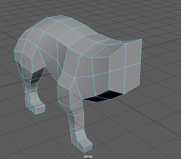
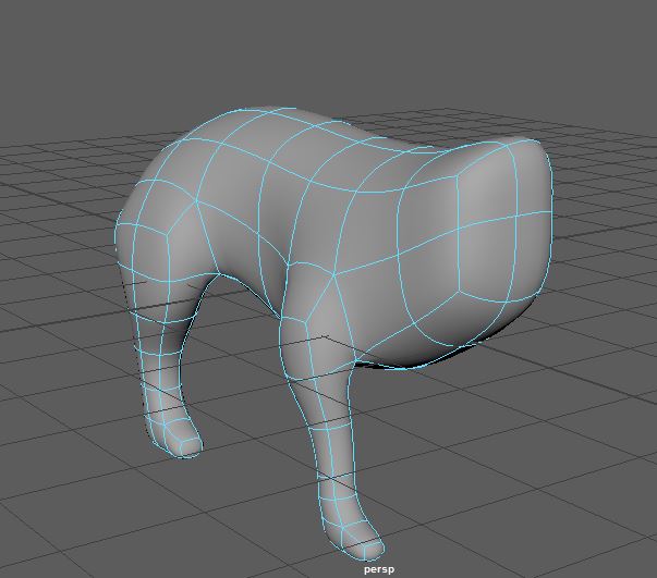
Here it is smoothed out.
Let’s see how our fox looks like with 4 legs. Go into top view mode, find the vertices that represent the very center of the fox and with your translate tool, hold down x which will “snap” your vertices to the nearest axis. Line up your vertices so that they line up with the slightly thicker line on the grid. This is so that we can mirror our current mesh over the correct axis. If your vertices aren’t lined up on the axis line, you’ll get overlapping faces or a gap between your faces.
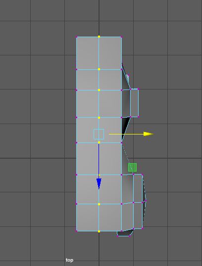
Once your vertices are lined up, select the faces on the left side of the axis and delete. Make sure to delete the side you DON’T want to keep.
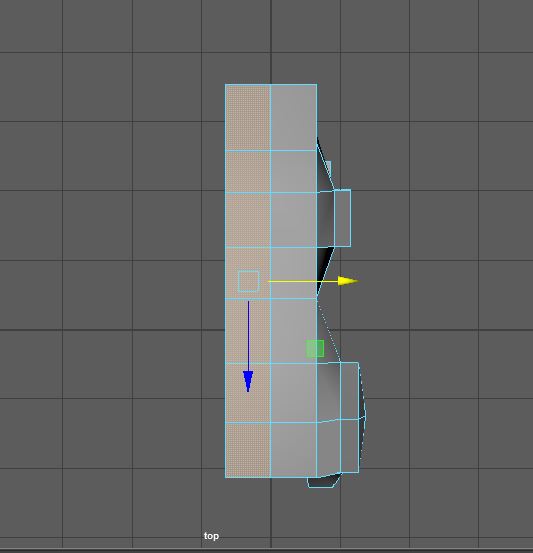
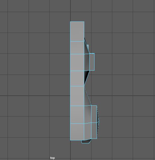
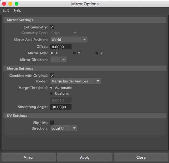
Next, with your object selected, click Mesh → Mirror Geometry → Option Box. In my scene, I’m mirroring over the x-axis to the negative side.
Play around with scaling the torso and legs of the model until you’re happy.
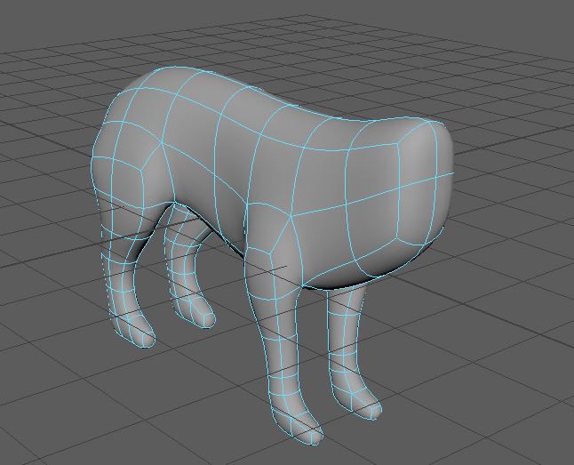
You can mirror geometry as often as you like! Use it to your advantage.
STEP 4: HEAD & TAIL
In your fox2.ma scene, Delete History, Center Pivot (if its not centered) and Freeze Transformations. Remember the shortcuts for these options as well as these are things you want to do in your files on a somewhat regular basis.
Override your foxLatest.ma by going to Save As and clicking on it to Save. Make sure to also Save As a new fox3.ma file and check that you are working in fox3.ma.
As before, select the outward faces and extrude your faces to match against the image in side view mode.
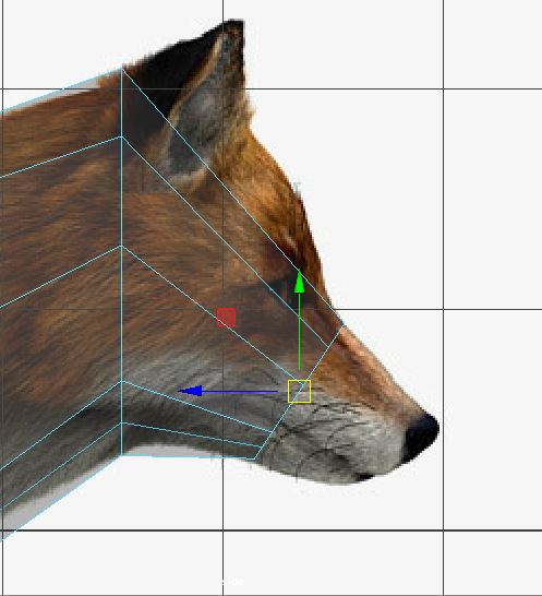
For the face, be very very careful as to where you add edge loops. We’ll leave the eyes until after the ears, so for now, make sure that you have edges at the front and back of your ears.
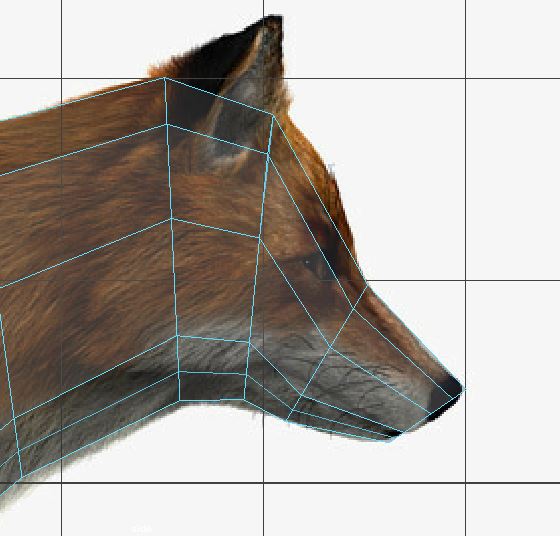
You can choose to do either the extrude method or the stitching method. Because the ear will be offset at an angle, I chose to use the stitching method because I can create the ear mesh freely and rotate it however I need to stitch it on. Depending on the situation, you’ll want to use a different method. For example, I prefer using the extrude method for limbs because I can just extrude straight down.
First, create a new cube. Like we did with the back leg, keep in mind how many vertices need to be stitched (in my case, 4 pairs) and match the cube with the reference image like so.
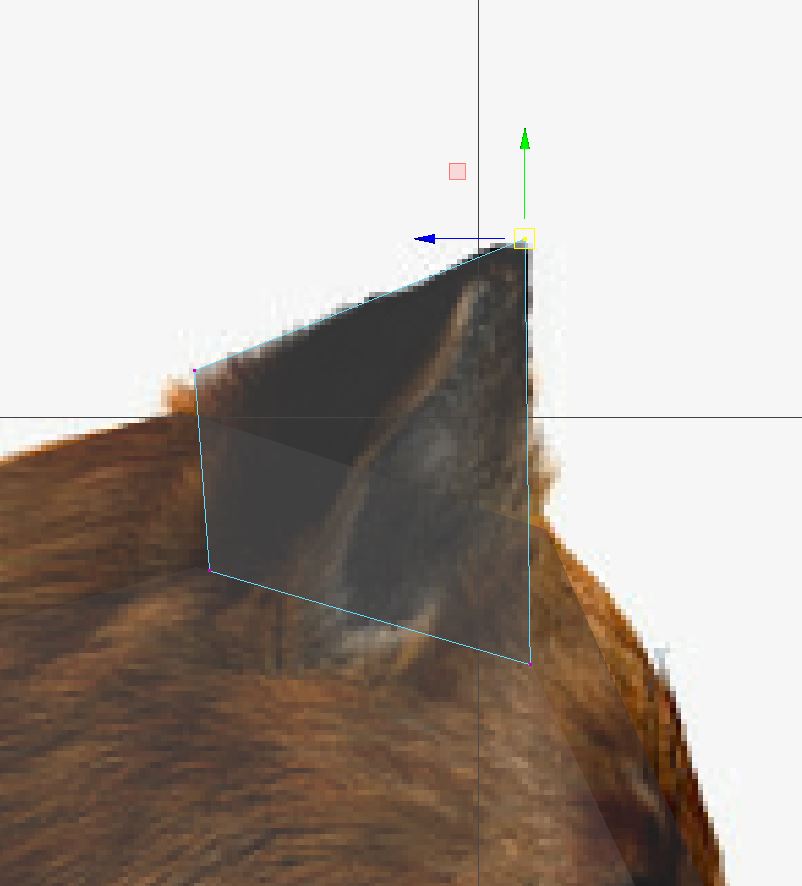
Add more edge loops like so. Match vertices against the image.
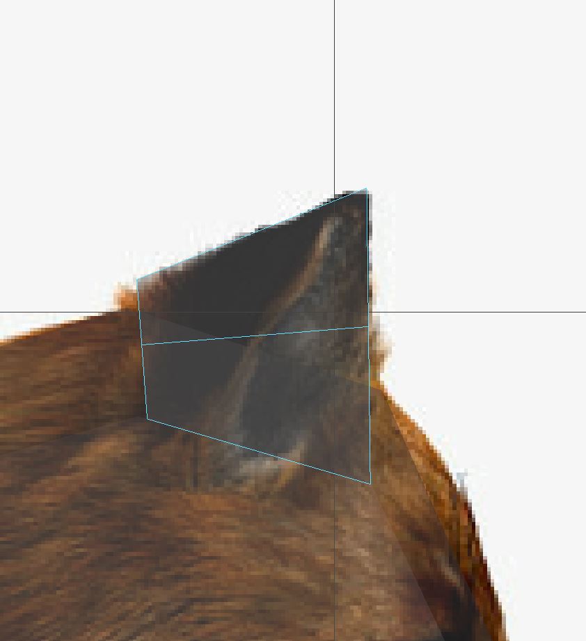
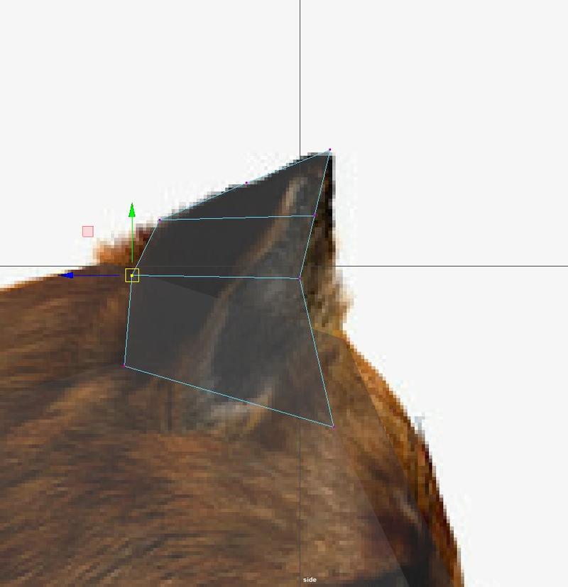
Select just the edge closest to you. Try to replicate how the ear in the image points outward by selecting this outer edge and pulling it back.
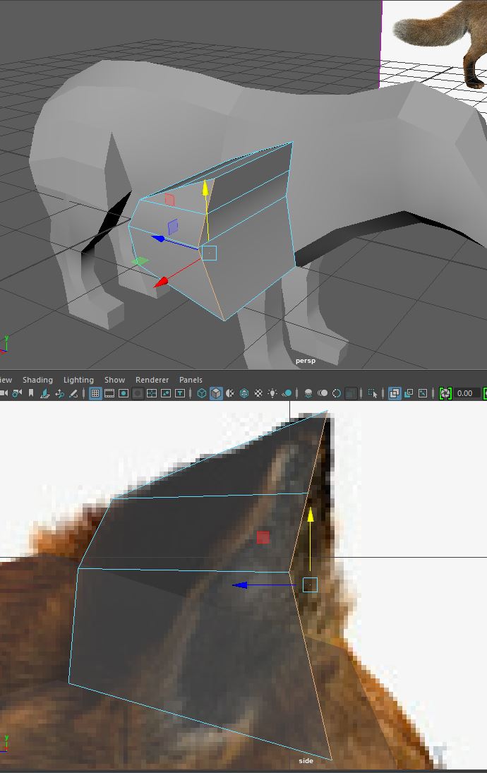
As you pull that edge back, make sure to scale the edge down to fit smoothly with the shape of the ear.
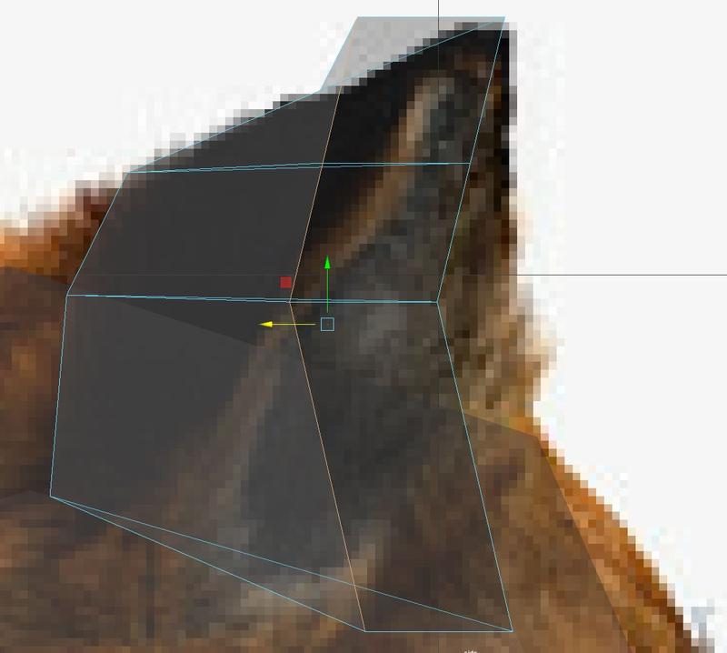
Like so.
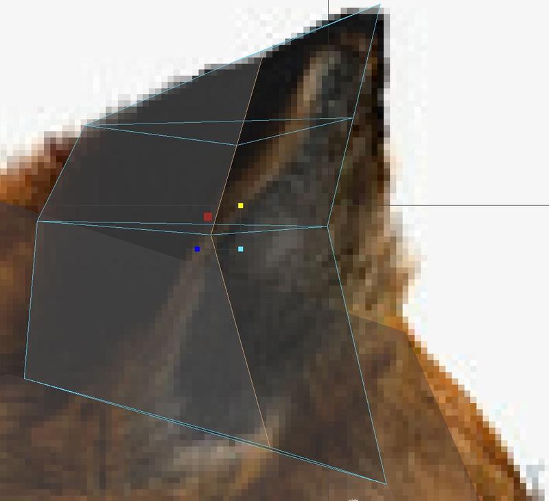
Using the scale tool, straighten your edges to get clean lines like this.
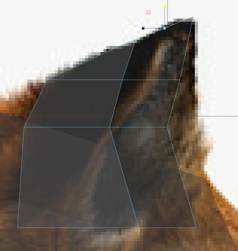
Select the faces that represent the inside of the ear, extrude, and scale inwards so your ear looks like this.
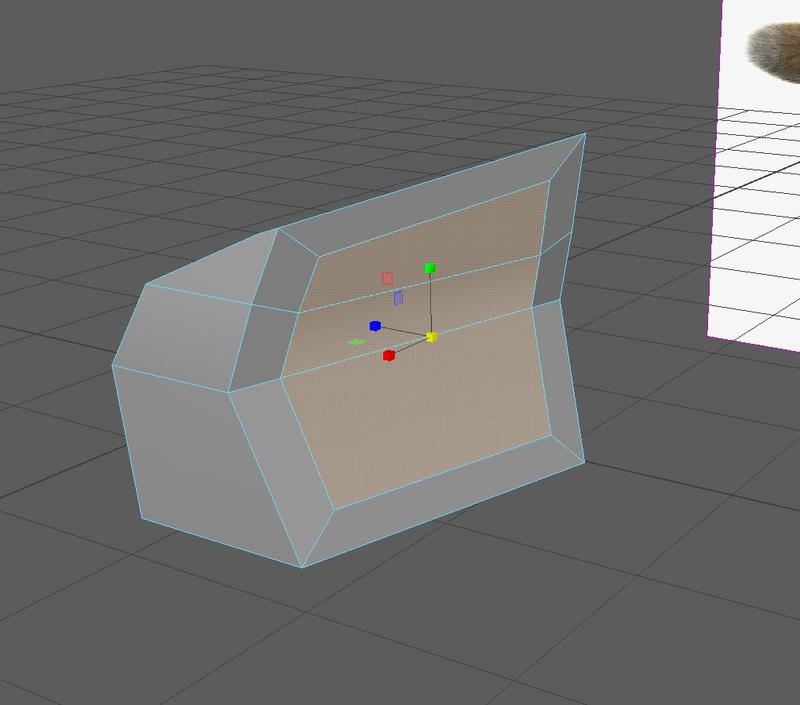
Extrude and scale once more and push in towards the back of the ear to get two segments.
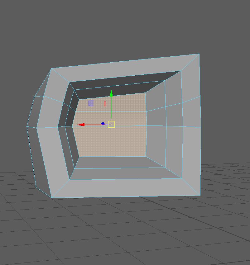
Select the top half of the faces and scale inwards to start tapering your ear. You can opt to use the Soft Select tool (Shortcut: B) for this.
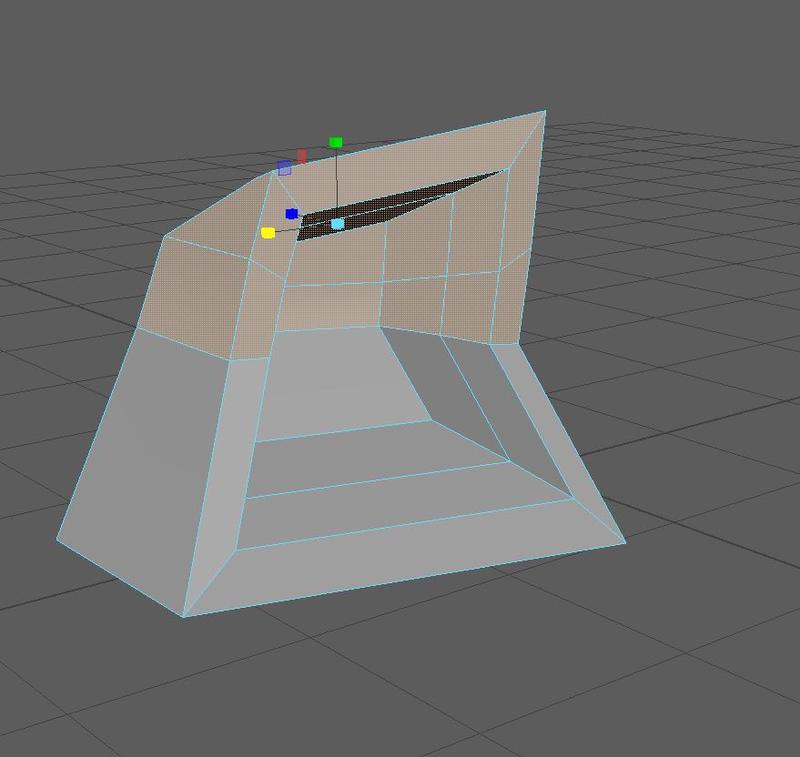
Continue tapering.
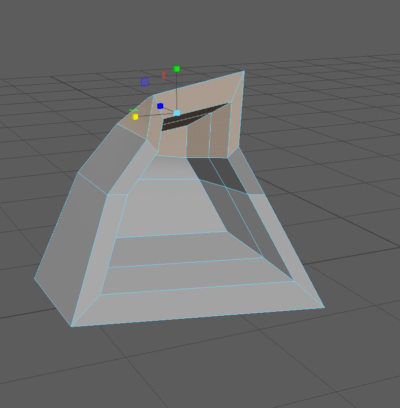
Spend some time fixing edge flow and straightening out kinks.
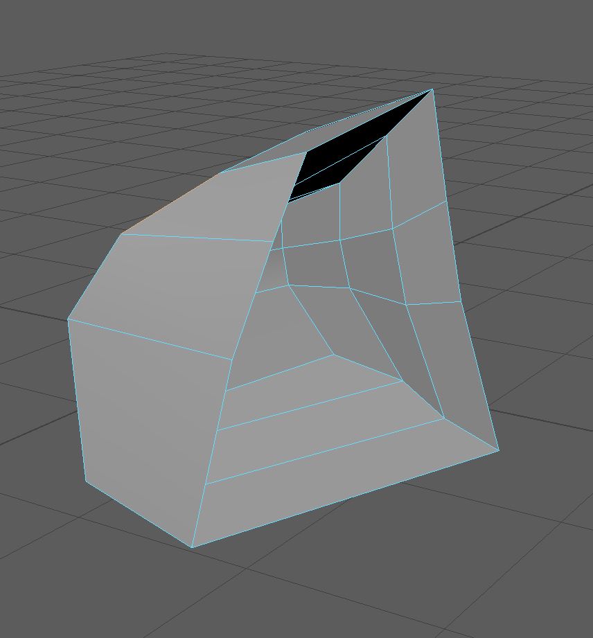
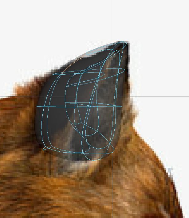
Go into smooth mode and manipulate your ear to match against the image. You’ll often find that your mesh is a LOT smaller than expected once you smooth it so you’ll want to adjust. Don’t worry if your mesh looks a little too spiky when you’re not in smooth mode but do note that we want our hard surface mode to be less drastically different than our smooth mode so try to straighten out the bigger kinks.
Like we did with the back leg, bring your ear mesh close to where you’ll be attaching it on the fox mesh.
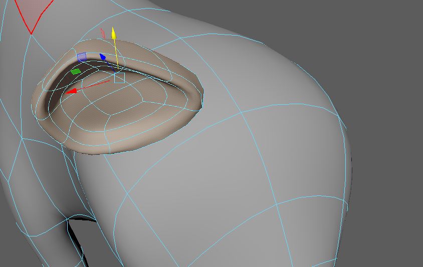
I found that my ear mesh was a lot smaller than the original face so I selected the face on the fox, extruded, and scaled inward until the vertices lined up with my ear’s vertices.
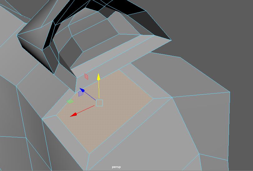
Again, delete the faces that are going to be stitched.
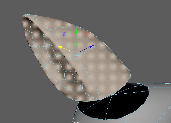
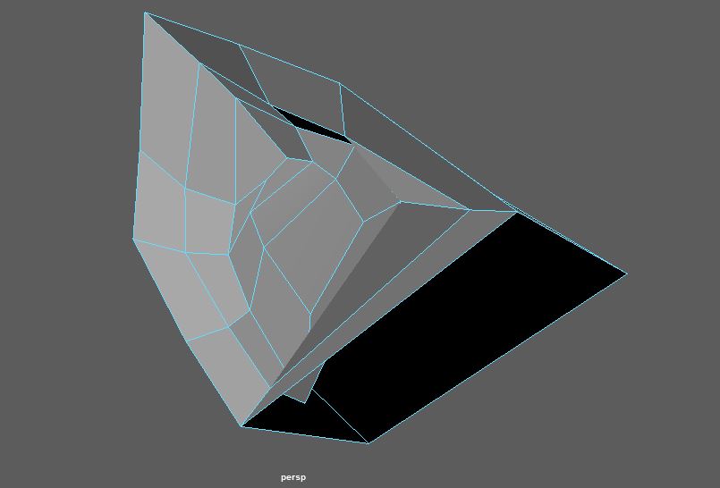
Select both meshes, go to Mesh → Combine. Go into vertex mode and begin stitching vertices together using Edit Mesh → Merge to Center.
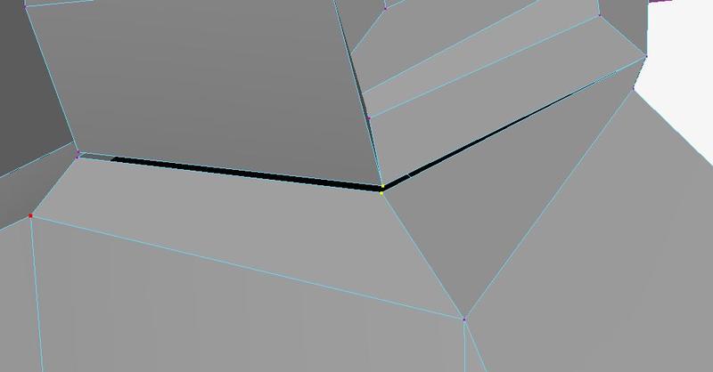
The sealed mesh should look something like this.
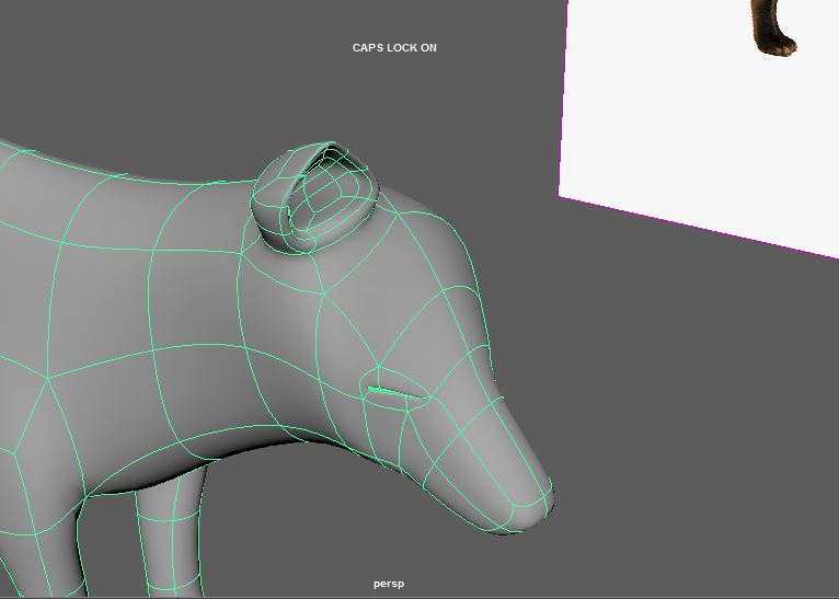
Again, spend time matching your smoothed mesh with the image and making adjustments.
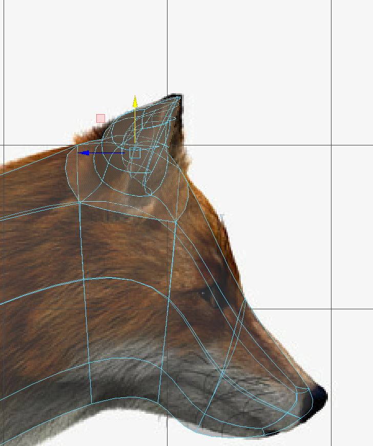
Since I didn’t have a front reference, I went ahead and mirrored my geometry again to see if the location of the ear looked normal. Adjust as you see fit.
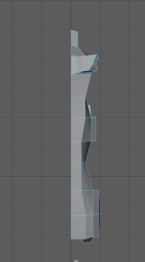
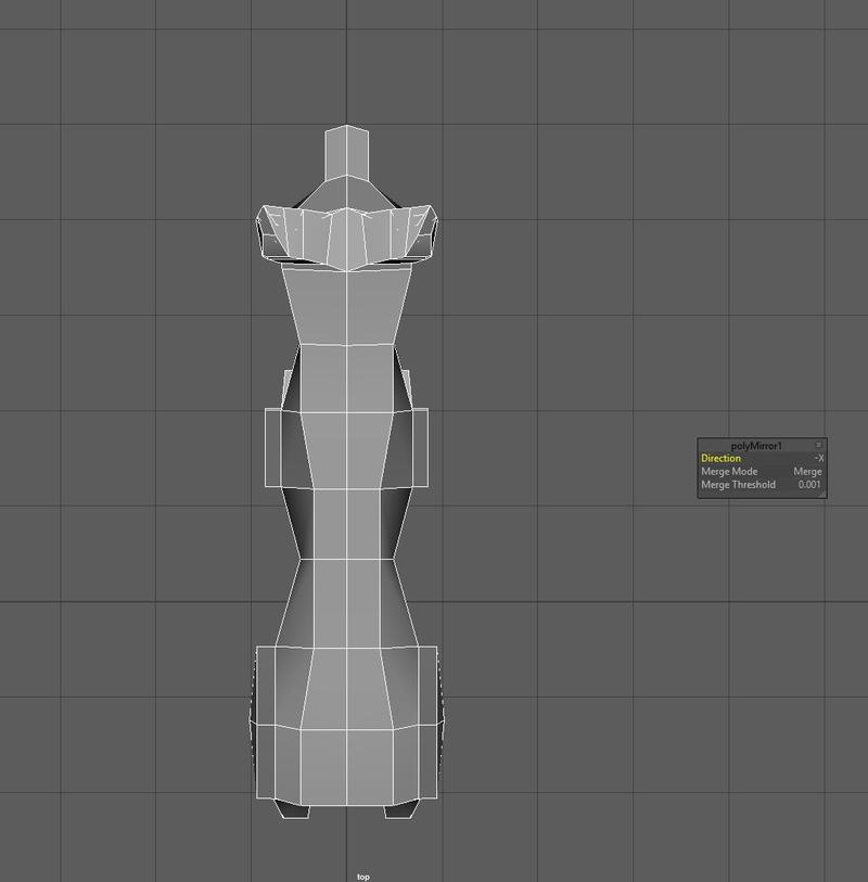
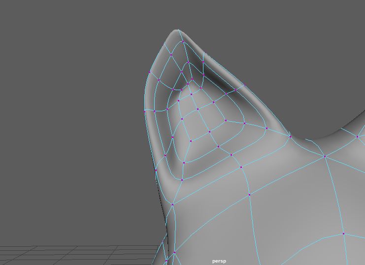
Adjust the ears as you see fit. I pulled the vertices up using soft select to make them more pointy and ended up with this.
Now onto the eyes. Back in side view, insert edge loops where the eyes start and end.
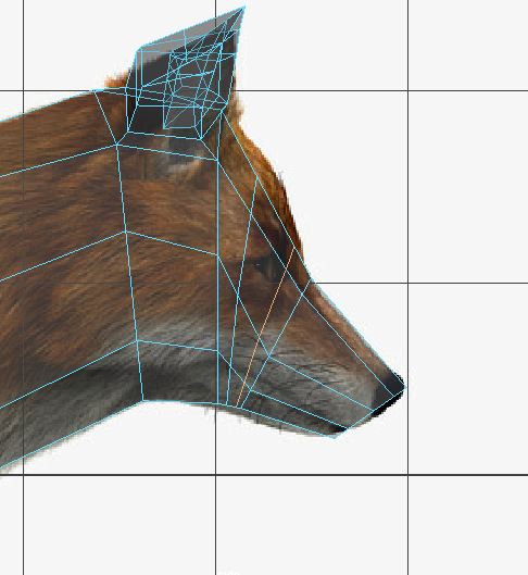
Adjust the vertices like so. The vertices follow the slope of the forehead and there are 4 vertices roughly outlining the eyes.
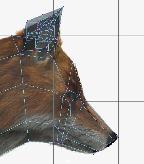
Take that face and extrude and push into the mesh.
There are many ways to make eye sockets. Some people will delete the face and extrude the edges inward only to seal it up later.
Whichever method you choose, make sure your mesh is “watertight”, that is, there are no holes in your mesh.
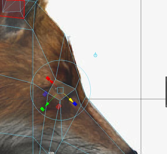
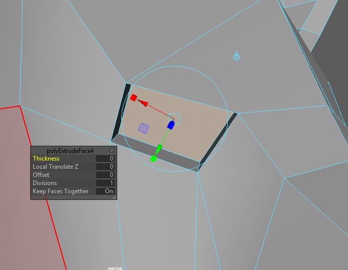
I’ve extruded inwards a few more times and scaled the edges up so that I have a balloon inside the fox’s head.
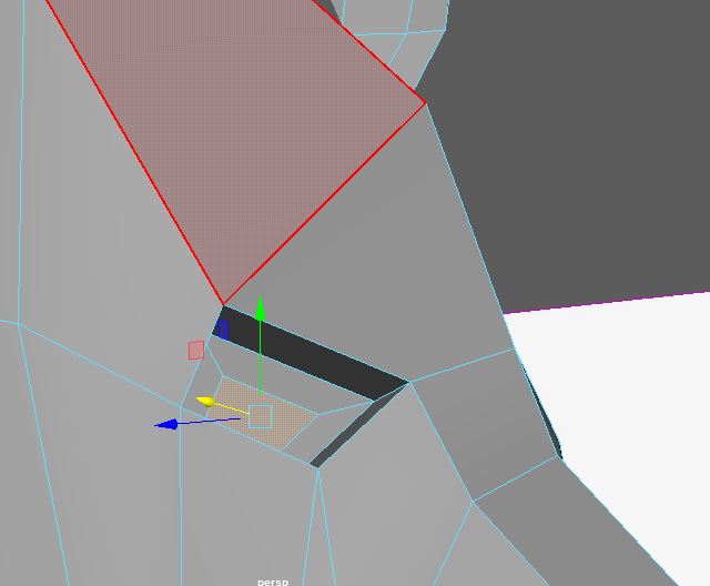
Here it is in smooth mode.
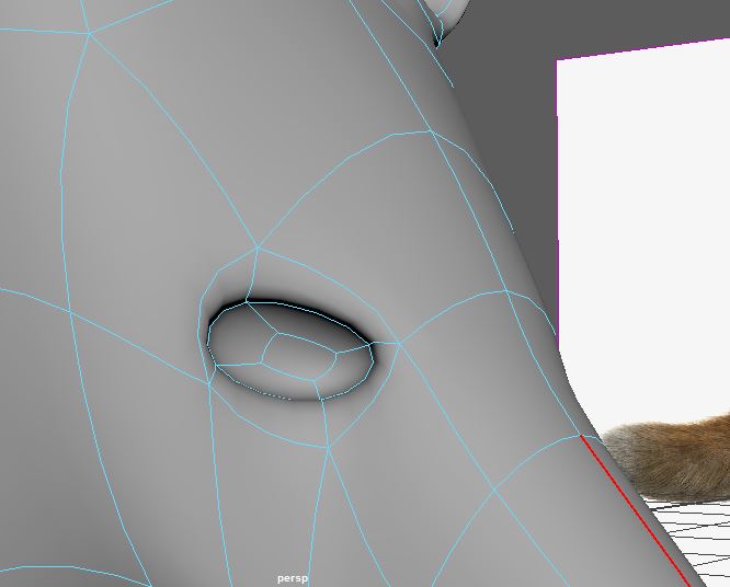
Along the edges of the eyes, add a few more edge loops. Because your mesh will be different from mine, you may need more or less than the four I’ve added here. Basically, add enough edge loops so that you can easily pull down these vertices to close the eyelid.
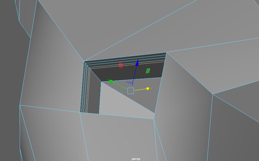
Use the Soft Select tool to grab the vertices around the top lid and translate down. Check your side view so that the eye is still lined up with the image and check your top view so that your eyelid isn’t sunken in.
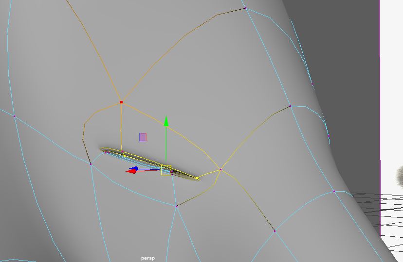
At this point, it might be a good idea to delete history and freeze transformations and save your file as fox4.ma and override foxLatest so we can start on the nose.
First, insert an edge loop behind the front of the nose like so. This is more of a marker for me for where the nose should end. It’s a lot farther back than seems normal because I’m compensating for smooth mode.
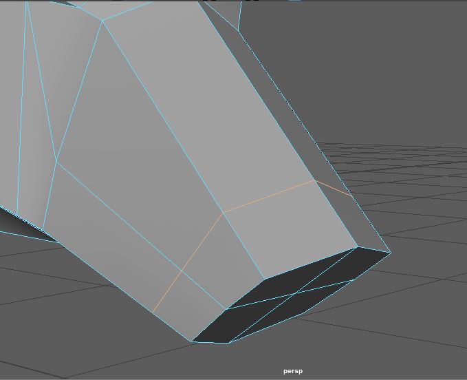
Add two more edge loops for each side of the nose. The nose is going to occupy this space.
Notice that my edge loops went ALL the way around the fox. Generally, I try to avoid this but I know that I’m going to have to make a tail at some point and these nose edge loops line up nicely where the fox’s tail will be.
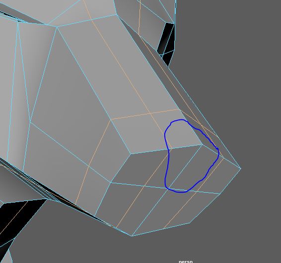
Like we did with the eye socket, select the face, extrude, scale inwards, extrude, scale inwards, extrude, and translate back. Try to get something like this.
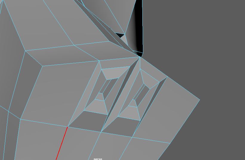
This is what it looks like in smooth mode.
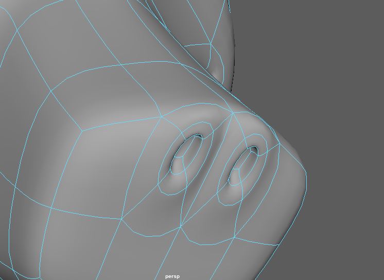
I added another edge loop which will be the end of my nose.
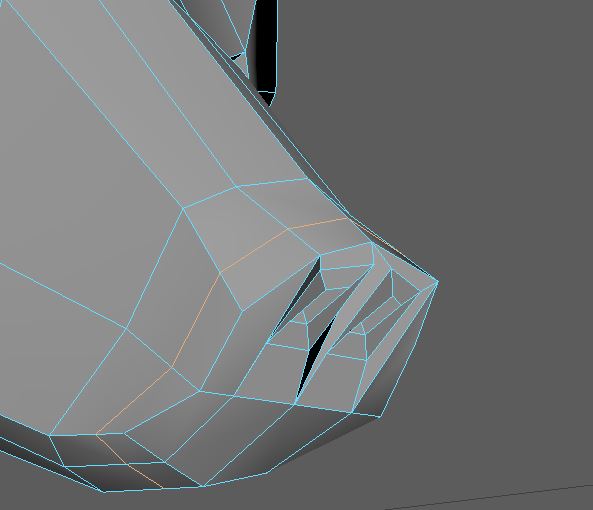
Select the faces limited by the newest edge loop and extrude outwards.
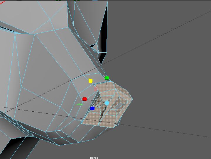
Scale, translate, etc. until your nose looks about right. I did a lot of tweaking around until I was satisfied.
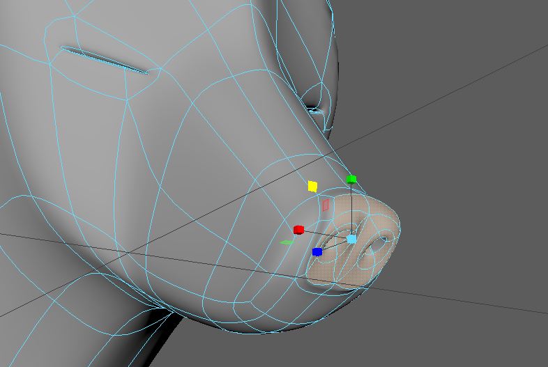
On to the mouth!
Look for a cut along the mouth in side view.
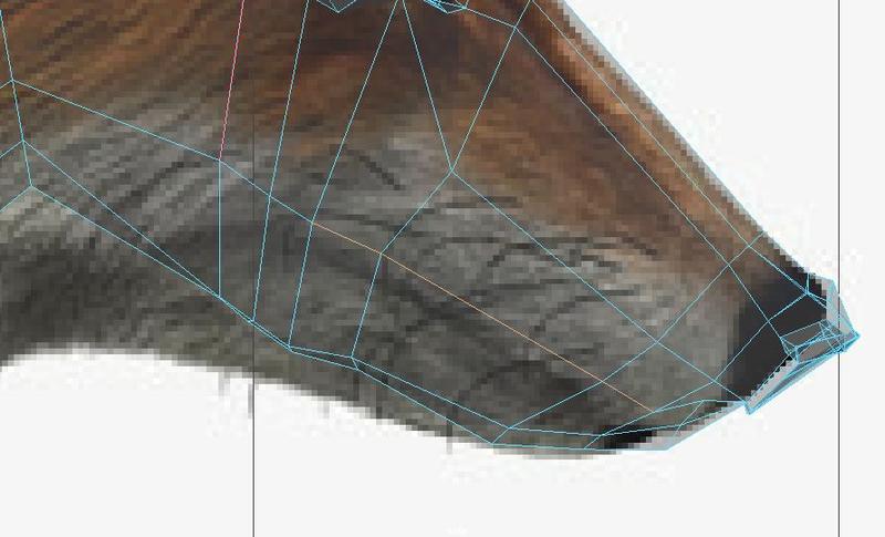
With that edge highlighted, click Edit Mesh → Detach. Move the edges apart so you can differentiate from the top and bottom sections.
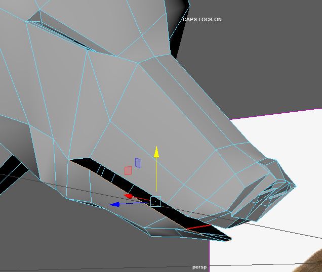
Our mouth has been made but now notice how we can see the inside of the fox from the mouth. Generally, if you ever see black polygons, that means that we are seeing the inside of the mesh which is something we NEVER want to do.
To seal up the gaping hole, go to Mesh Tools → Append to Polygon
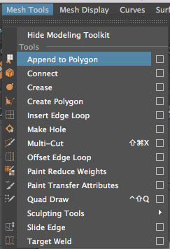
As shown in lecture, Append to Polygon is a very useful tool to seal up holes in your mesh by creating new faces/vertices and appending them to the existing edges. For our case, we want to create faces over the bottom and top of the mouth.
Let’s start with closing the bottom jaw:
First, rotate and move your camera so that you can see the inside of the fox’s mouth.
(interesting view isn’t it)
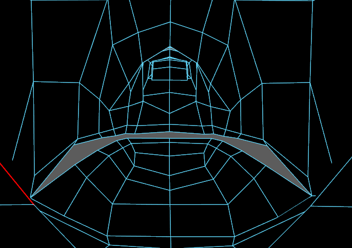
Then, with Append to Polygon on, select the left edge on the bottom jaw of the fox. Once you do, you should see purple lines and arrows indicating to you which other edges you can select to create a new face.
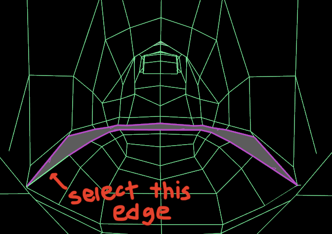
Now select the right edge on the bottom jaw of the fox to complete the appended face.
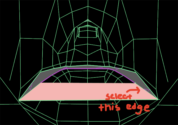
Then press enter to create the face.
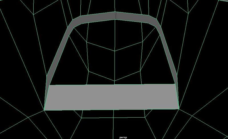
Continue using the Append to Polygon tool. It might be handy to use the g hotkey to go back to this tool easily.
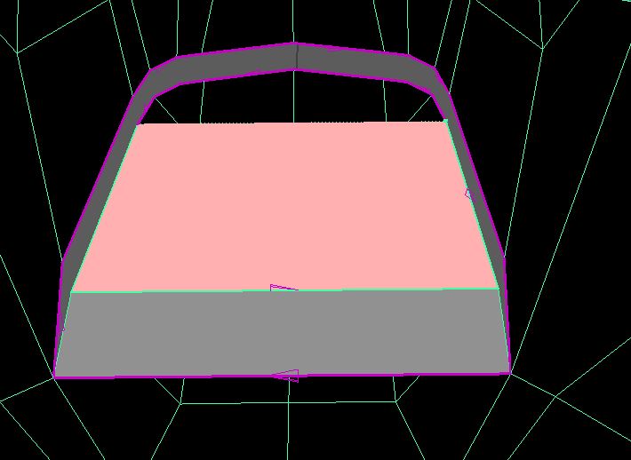
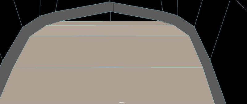
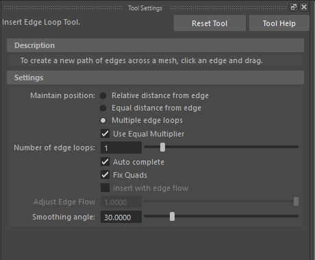
The problem we have here is that if you were to close up this last hole, you’d have a 3 sided polygon. To avoid this, go to Mesh Tools -> Insert Edge Loop Tool -> Option Box.
Change your settings like so. The idea is to get 1 edge loop right in the middle of the mouth.
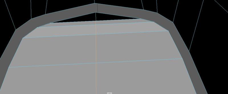
When you use the tool you should have something like this.
Click and drag the new vertex you made so that it’s near the end of the mouth.
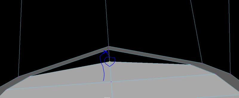
Select both vertices and click Edit Mesh → Merge to Center.
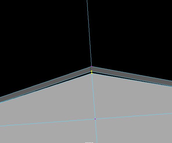
Like so. Now do the same for the roof of the mouth.
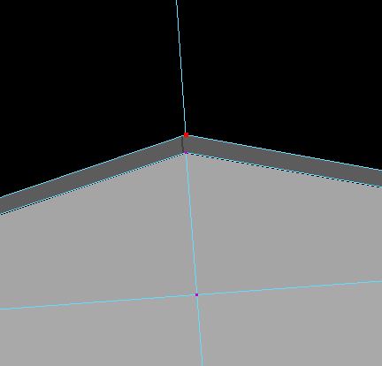
Don’t forget to also merge the center vertices at the back of the mouth.This should finally seal the mouth.
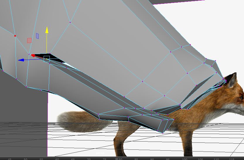
Back in side view, match your vertices up along the outline of the mouth but make sure the vertices don’t overlap completely. You don’t want faces cutting into each other.
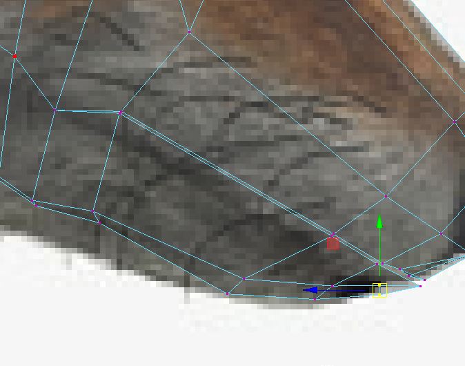
After a few cosmetic tweaks here it is in smooth mode.
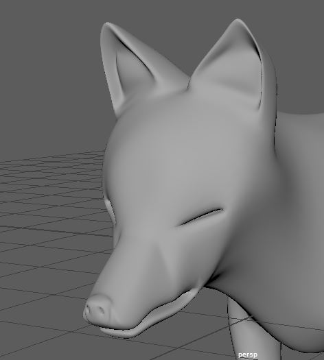
Before we get to the tail, select half the faces, align vertices by using the x snap tool, and mirror geometry.
THIS WILL BE A LOT EASIER IF YOU TURN OFF Retain component spacing. Look at the HANDY TOOLS section for help.
Feel free to delete history as well.
Start off by selecting the faces around where you’d want the tail to start.
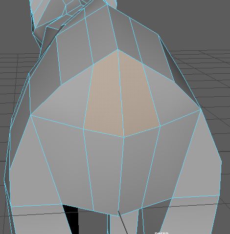
The faces are a bit too big so I extruded them and scaled inwards twice. You may choose to do more or less.
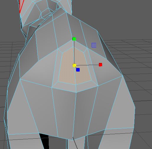
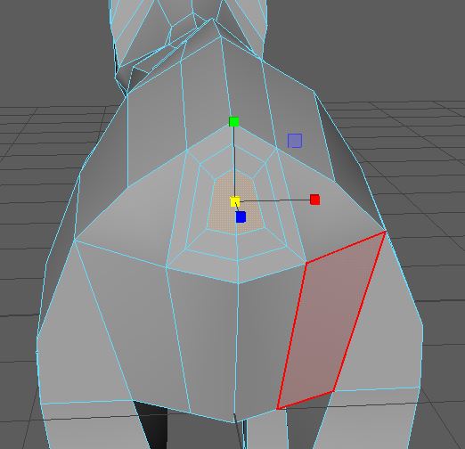
I extruded once more and went into side view to pull out segments of the tail.
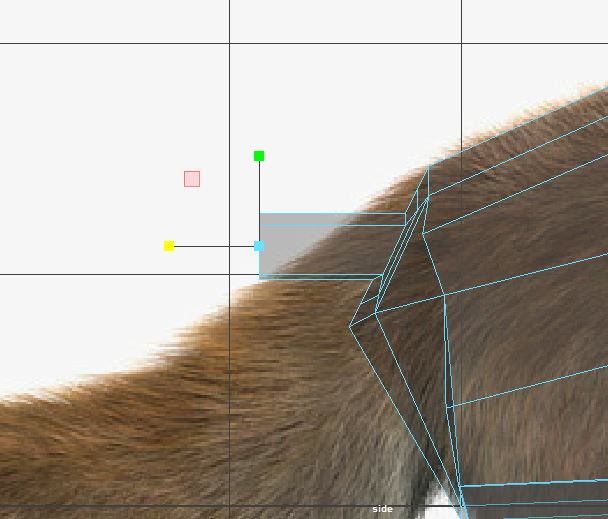
And out and out and out!
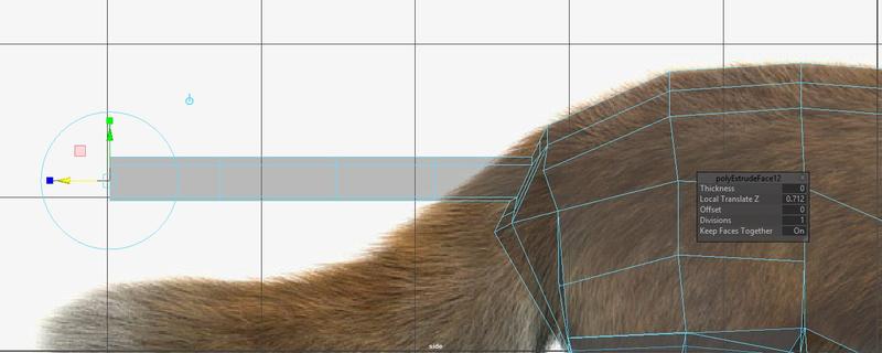
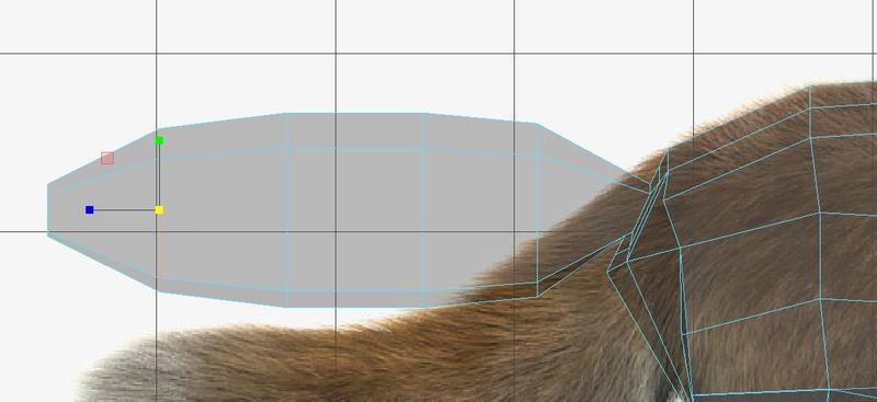
Then I scaled it up to make what I think a fox tail would look like. It’s out straight because I’m lazy but also, this makes more sense when rigging/skinning. Much like how we ask you to model bipedal characters in the T or A pose.
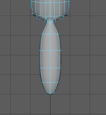
Check your top view!
And finally, tweak, add edge loops, move vertices, all that good stuff to get in the DETAILS. This is including adding more edge loops at joints, rounding out sharp corners, and if you’re feeling adventurous, making claws and teeth.
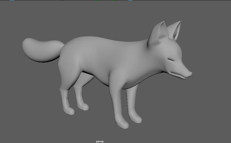
This is what my fox looks like after a couple tweaks. This is where I’ll stop for the purposes of this lab.
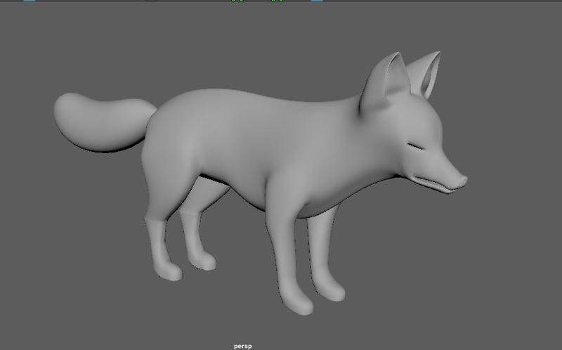
Make sure not to forget to do one last thing (hint, hint).
LECTURE TOPICS NOT FULLY COVERED BY THIS LAB:
DEFORMER
To create a deformer, go the the Deform menu, which has a list of useful deformers.
Here are a few useful ones:
Nonlinear → Bend (does exactly what you think it does)
Nonlinear → Twist (does exactly what you think it does)
Lattice (Creates a cube around your mesh, and you can deform your mesh by deforming the cube. This helps when your mesh is too complicated to make large manipulations. Make sure you use the option box to set the number of divisions)
In order to use a deformer, select your mesh, and then click on the deformer in the deform menu. If you use bend or twist, play with the values in the channel box. If you use the lattice deformer, switch to vertex mode and edit the points on the lattice.
Remember, deforms create a field that affects your mesh but does NOT permanently deform your mesh.
Once you are done applying a deformer to a mesh or a piece of a mesh, select your mesh and press Alt + Shift + D to delete history. This will get rid of the deformer. Try using a bend deformer to bend the tail of the fox! Make sure to play with the curvature, the high bound, and the low bound, and move the deformer so it only deforms the tail.
SCULPT
Sculpting is better done in software like Zbrush (very expensive!) or Autodesk Mudbox (free for students!) but you can emulate these sculpting programs using the Mesh Tools -> Sculpting Tools. Play around with Sculpt, Smooth, and Grab. Make sure to mess with “Mirror” and “Invert” in the tool settings. The idea behind Sculpt and Grab is to pull and push in your mesh to achieve the bumps in organic models caused by muscle groups, bones, knuckles, and the like. The Smooth tool is particularly useful when your vertices/edges/faces are irregular in certain areas, even when your mesh is relatively low poly. It can often be a quick way to deal with messy topology.
At this point, feel free to use the Sculpting Tools (or any other tools) to make aesthetic changes to your fox. The more detail the better!