INTRODUCTION
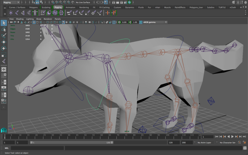
Before following along with this lab, you should complete the RIGGING 1 LAB, which walks through the process of creating a skeleton for a fox and placing the IK handles. We want you to revisit these steps so that you have a solid foundation of the very basic steps of rigging before moving into advanced methods. (That lab shouldn’t take you very long so don’t be too overwhelmed)
This lab will effectively act as a continuation of the Rigging 1 lab, but as opposed to the “Rigging 2” lab you did in basic UCBUGG, you will now do the Advanced Rigging Lab in which you will rig the fox in a much more advanced way.
ADVANCED CONCEPTS COVERED:
This lab is split into two weeks, so work only until the designated sections for the appropriate week.
- Creating Custom Controllers and Locators (Week 1)
- IK Splines (Week 2)
- Using the Connection Editor (Week 2)
CHECKING ON WORK SO FAR (Week 1)
This is the start of the Week 1 section:
-
After completing the Rigging 1 Lab, you should have a skeleton that looks like this:
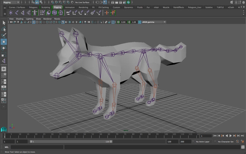
Notice that I did actually change one thing: the position of the root joint. Previously (in Rigging 1), the root joint was in the middle of the spine. That isn’t too much trouble for creating a very basic rig, but for this rig we want to go a little bit more advanced, so let’s make the hip joint the new root.
To do this, select the hip joint, then go to Skeleton—>Reroot skeleton. Now the new root is the hip joint. -
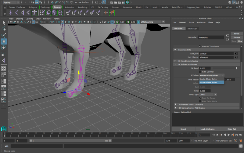
You also already have your ik handles. Make 100% sure that they’re all set to the “rotate-plane” solver, NOT the single chain solver. To check this, select the ik handle, open the attribute editor, and check here:
CREATING AND PLACING CUSTOM CONTROLLERS FOR THE FEET
In case you don’t remember, you should never be animating by directly selecting joints and rotating/moving them. You need some in-between controllers that you can control that then indirectly alter the joints. So, we need controllers. You’re probably used to creating/seeing circles for controllers, but that’s beginner stuff. You’re advanced and therefore you’re awesome, so let’s get a little deeper into controller creation.
-
Go to Create—>Nurbs Primitives—>Circle. Move that circle to one of the front feet (doesn’t matter which one, you’ll duplicate anyway when it’s done).
-
Match the pivot of the controller to the pivot of the foot joint. To do this, hold “d” and you’ll see move arrows appear, allowing you to move the pivot of the controller. This isn’t enough, however, because you really don’t want to be eyeballing the pivot’s correct location. So, also hold down “v” while holding down “d” and it’ll snap the pivot to points (meaning that it will only allow you to place the pivot at certain points—not in between them). Match the pivot to exactly the middle of the foot joint. This is what the general process looks like:
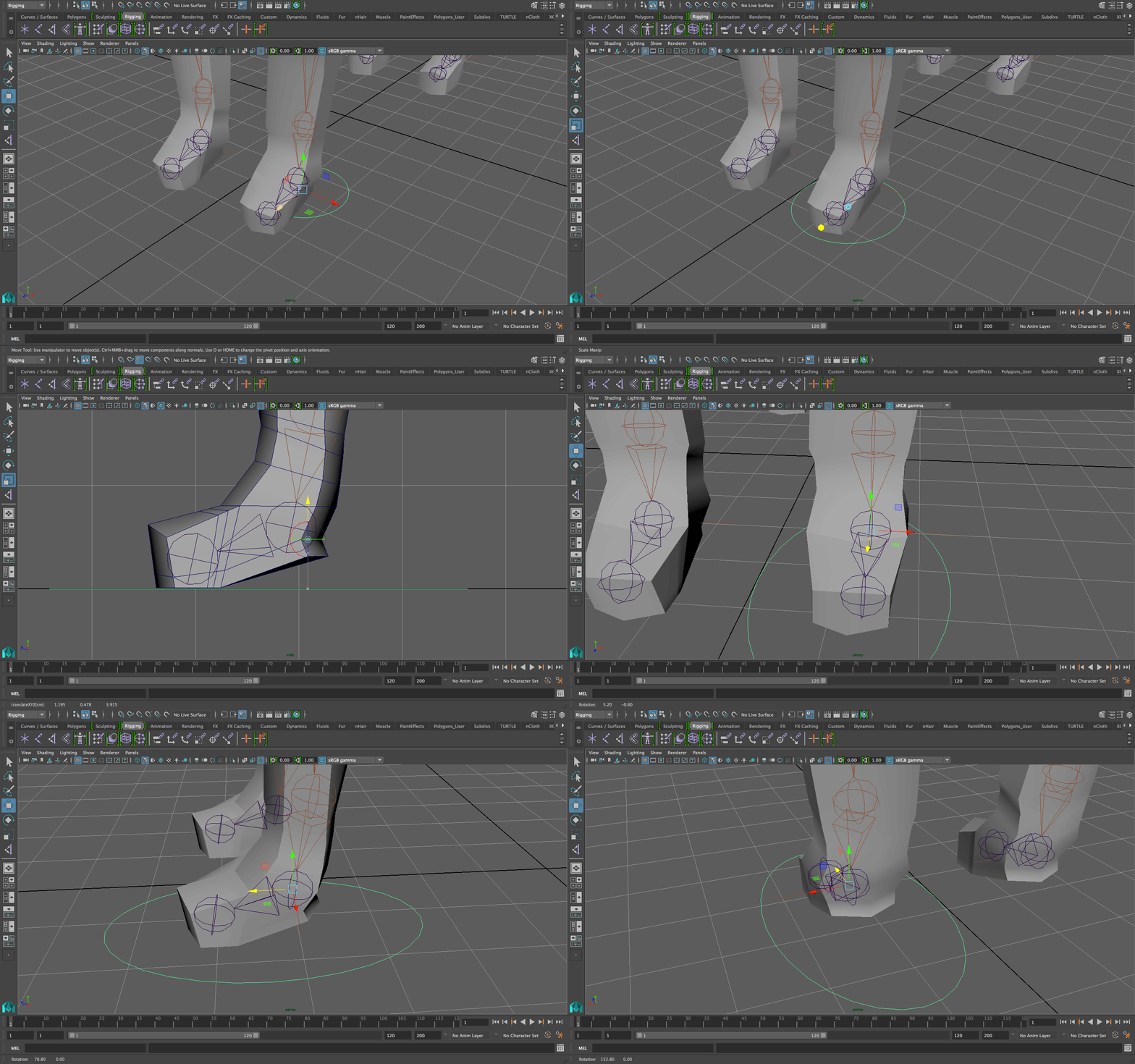
Why did we just do what we did?
We want the rotation of the circle to match the rotation of the foot joint. If their pivots don’t match, they’re not going to rotate from the same center point.
This is what it would look like if the pivots were not matched (remember, this is WRONG):
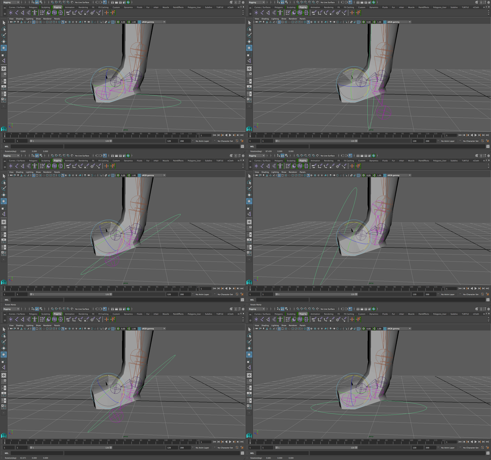
And it would actually get worse with carryover movements (i.e. if you do this for the head and then move the shoulders, the head controller would be even more off than it was before.)
-
Resize the controller to get it to look like a more adequate controller for the foot. Perfect circle isn’t very practical. You also don’t want the controller intersecting with the mesh, so resize as needed. For mine, I made it a little more oval-like so that it fits better with the foot.
-
Now, for the more advanced element of making controllers. Before getting into customizing your controller, I want to show you an example of why circle controllers for feet/legs suck. This is the situation you’ll unfortunately find yourself in many times if you’re using flat circles for feet controllers:
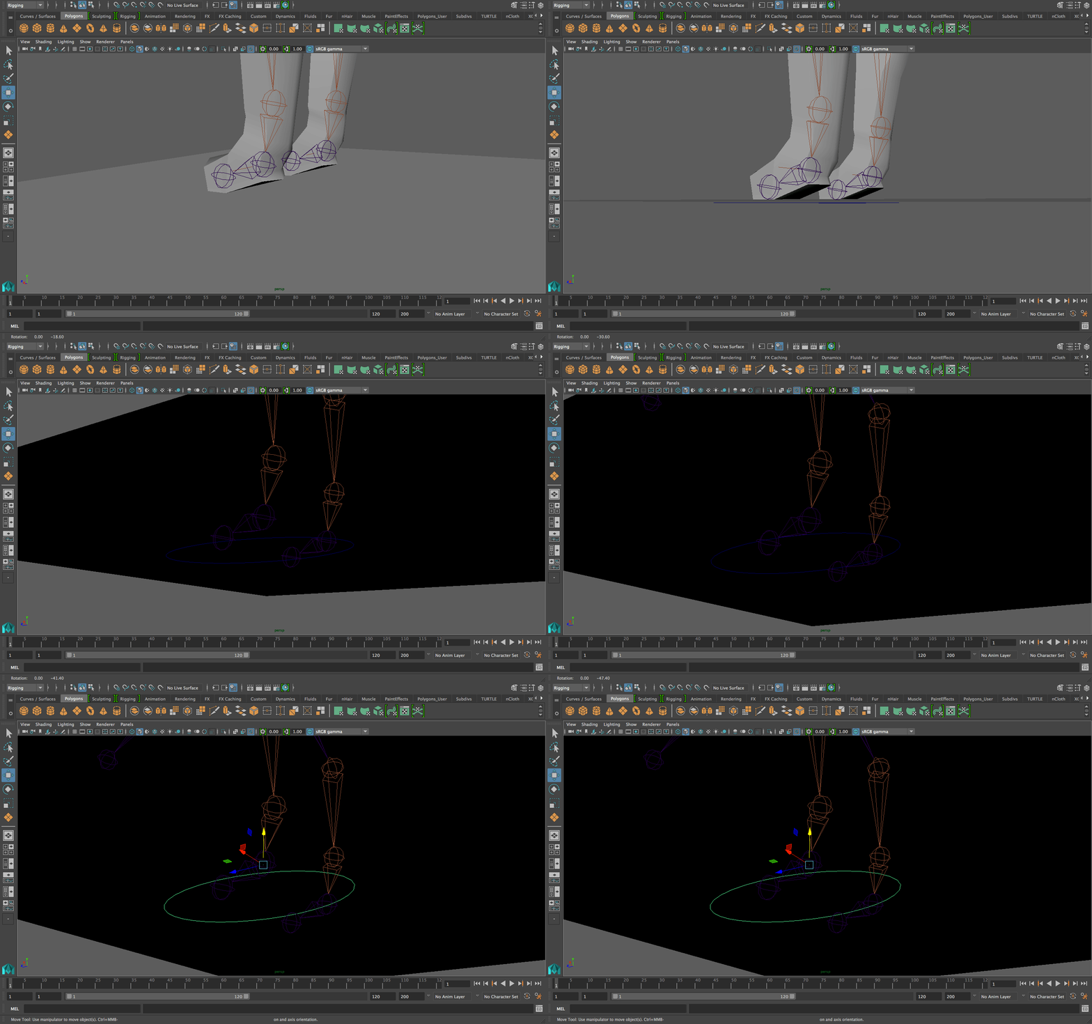
They’re under the floor!! So accidentally you’re going to find yourself leaving the controller on top of the floor so that you can see it. Then when you add your lights and render you’ll realize that your character isn’t completely touching the floor, so you’re going to take all the translate-y animation curves and move them just a little down so that they are touching the floor. Not fun.
Another potential problem: if all your controllers are circles, then when your character is in a position where their body parts are closer to each other (i.e. the character is crouching or squashing in preparation for a jump/run, etc.) you’re going to find a bunch of circles, all intersecting, and you’re going to wonder which controller corresponds to which body part. This can be incredibly annoying and an absolute waste of time. Now I’m going to show you how to avoid this. -
Hold right click on the circle controller and go to “Edit Points” (this same task can be done by selecting “controller vertex” instead by the way). Move around the points to get a controller that doesn’t look flat and would be easy to select. Here’s the process of making my own controller:
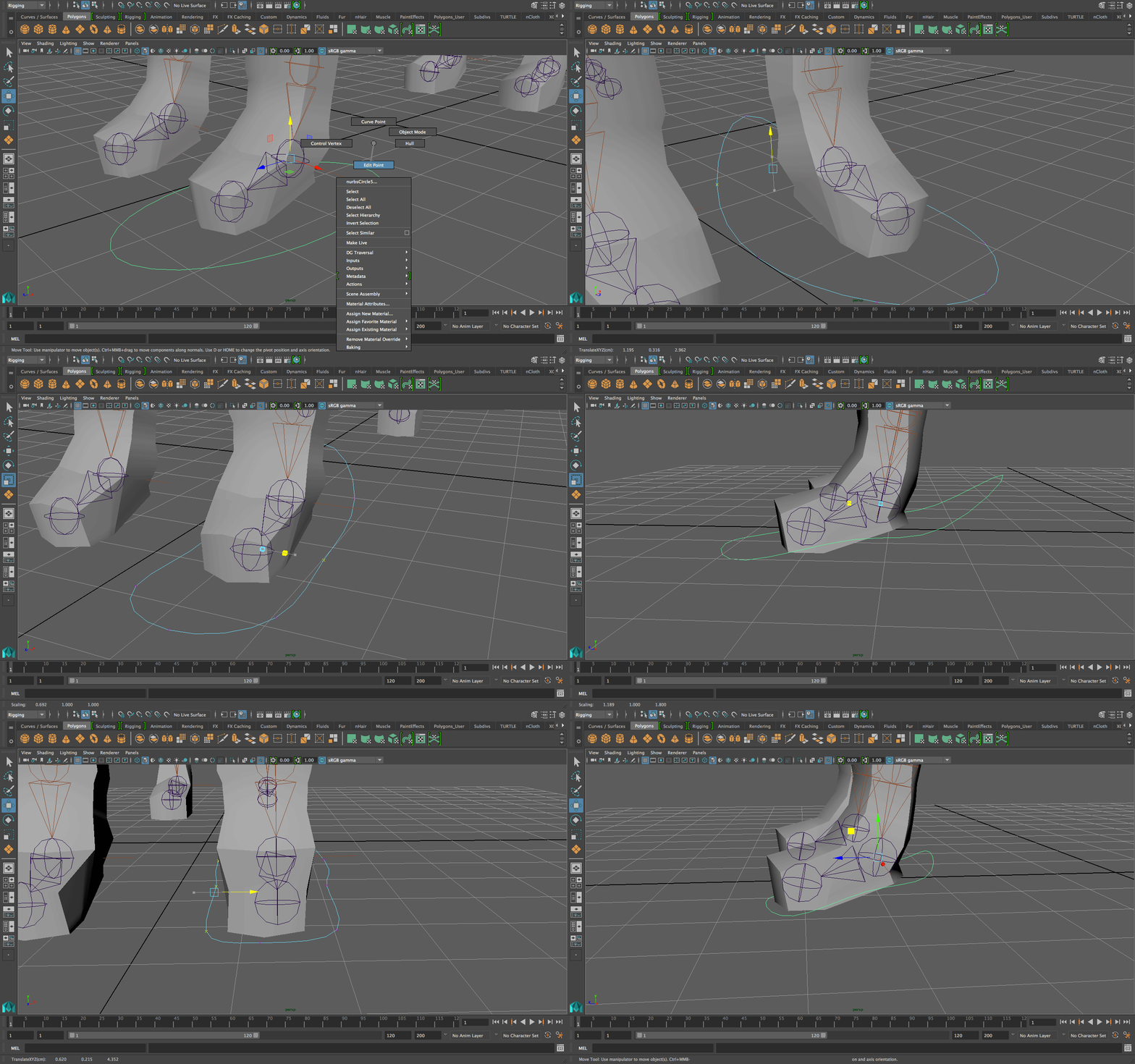
You do NOT need to match the same shape as my controller! Just make something that is easy to see, that makes sense, and that is easily selectable.
Tip: make the front end of the controller lowest (in line with the lowest part of the foot) so that if that’s intersecting with the floor, at least you know the fox’s foot is touching the floor.
Make sure the pivot is still exactly in the middle of the foot joint if you’ve editor the controller as a whole. -
When you’re happy with your controller, go to Modify—>Freeze Transformations and then go to Edit—>Delete By Type—>History.
Why did we freeze transformations?
Freeze transformations zero out a controller’s attributes. So instead of its translate value being some big number, it’ll be zero. Its place under the character’s foot with it pivot matching the foot joint is now its new “origin.” This means that if you move the foot away, you don’t need to eyeball its original position, you just need to make the translate and rotate attributes 0 and it’ll be back where it should be. This is absolutely essential for animators. -
Name the controller. I’m going to name mine left_hand_controller (I know it’s inconsistent to call them feet in the tutorial and then to name the front legs as hands, but whatever is easier to understand/recognize is better. So you can name it front_left_foot_controller if you like.)
-
Duplicate the controller and move it to the other foot. Match the pivot to the middle of the foot joint, freeze transformations, delete history, and you’re good for the other front foot. This is basically the exact same process as we did for the other controller. Rename the controller appropriately.
-
For the back feet controllers, we’re going to make boxes for controllers instead of circles. These are awesome because they’re so easy to see from a distance, and they’re 3-dimensional so they’re easy to select even if the foot is a little bit intersecting with the floor. (The reason we didn’t do boxes for the front feet is because I want to show you that there’s a range of custom controllers you can make, some of the circle-based, others line-based).
-
Go to Create—>Curve Tools—>EP Curve Tool and click the options box. Click on the “1 Linear” beside the “curve degree” option. This basically means that you’ll be making linear, straight lines as opposed to curves.
-
Remember how you held “v” to snap to points when matching the pivot? Now we’re going to hold “x.” Holding “x” will snap to grid points, meaning that you’ll only be allowed to make selections that match with the floor grid’s intersection points. So, while holding “x” down, make a rectangle around the back foot of the fox. Do not press enter yet! This is not going to be a flat rectangle!
-
Now, for the fun part: make the rectangle into a rectangular prism (basically make it 3d). Go to the side orthographic view and click one point above the foot. Then, continue the line to behind the fox’s foot (back to the point on the other side). When you’re done with that side, move onto the “front” orthographic view and make the front rectangle of the controller. Again, you’re basically making the outline of a box.
It is absolutely okay to go over the same line more than once. In fact, it’s necessary to be able to make a rectangular prism. So don’t worry if you find yourself clicking on the same point again. Just focus on the result in this step: a rectangle.
It is NOT okay to make it in separate lines. Connecting lines can be very tricky (we’ll do it later in the lab when we’re making custom locators) but that’s going to be painful enough, so no need to go through the same ordeal now.
Here’s my process of making the box controller:
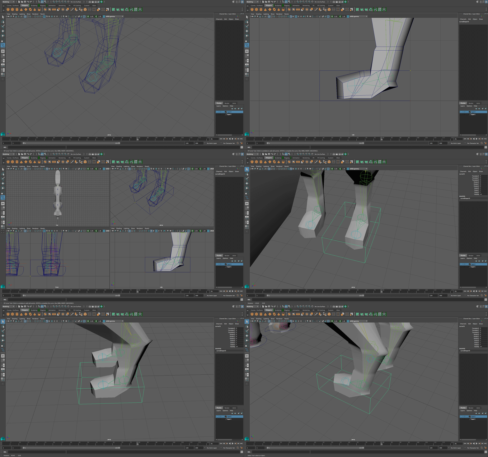
-
Match the pivot (by holding “d” and “v” and snapping the pivot to the middle of the back foot joint.)
-
There can be further editing if you like. I find it helpful to have the upper part of the rectangle a little scaled in so that it isn’t a standard rectangle (helps in identifying which way is up.) So go to “edit points” and grab the corners on the top side of the box and resize them inward.
You’ll want to click and drag a small box around the corners to select them. If you just click on them, there’ll be overlapping points and disconnected points. Anyway, here’s my process of resizing the controller top inward. Notice how I still need to center the pivot around the foot joint afterward (because I moved the whole controller):
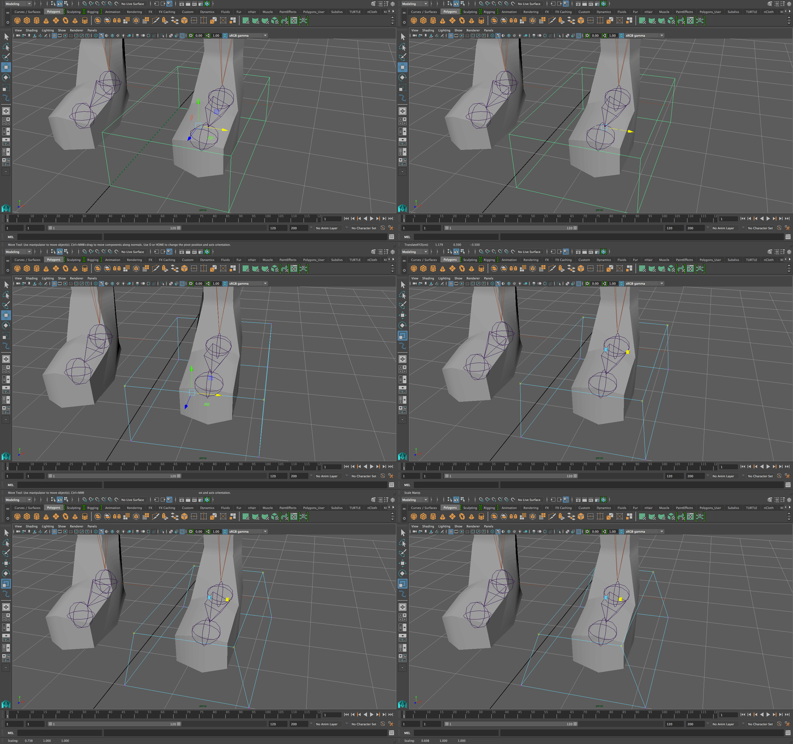
-
When you’re done shaping your controller, freeze transformations, delete history, and name it appropriately.
-
Duplicate the controller to the other foot and repeat the process: match the pivot, freeze transformations, delete history, and you’re good for the other back foot.
ATTACHING THE CONTROLLERS TO THE FEET
-
We’ll now make the controllers actually control the feet. This is a lot simpler than it sounds, actually, when you keep in mind that the controller must do two things: rotate the foot and translate (move) it.
-
To relate any two things in Maya, you need to use constraints. For rotation, we’re going to use an orient constraint, which is a constraint that relates/links the rotation of one object to the rotation of another object. The object doing the rotating is the driver/parent, and the object being rotated is the driven/child. When using anything under the constraints menu, we select the driver/parent FIRST and then the driven/child SECOND. So, select the controller, and then shift select the foot joint. Then go to Constrain—>Orient under the rigging menu and click the option box. Make sure the “maintain offset” is checked and then click “Add.” Now when you rotate the controller, the foot is going to rotate with it.
-
The other thing to do is to allow the controller to move the foot. For that, we’ll parent the ik handle to the foot controller. Notice that I said “parent” and NOT “parent constrain.” These are two different functions! Parenting just involves putting one object under the other in terms of hierarchy, but a parent constrain is a different way of constraining an object’s rotation, translation, and scale attributes to another object. So, select the ik handle, and then shift select the controller, and then press “p”
When you use normal parenting (i.e. clicking “p” or dragging one object under the other in the outliner) you select the child/driven FIRST and then the parent/driver.
When you use any constraint under the constrain menu, it’s the other way around: parent/driver FIRST and then child/driven SECOND. -
Now, try moving around the foot controller and rotating it. It should be behaving as expected, moving where it needs to move and rotating where it needs to rotate. Here’s what it should look like:
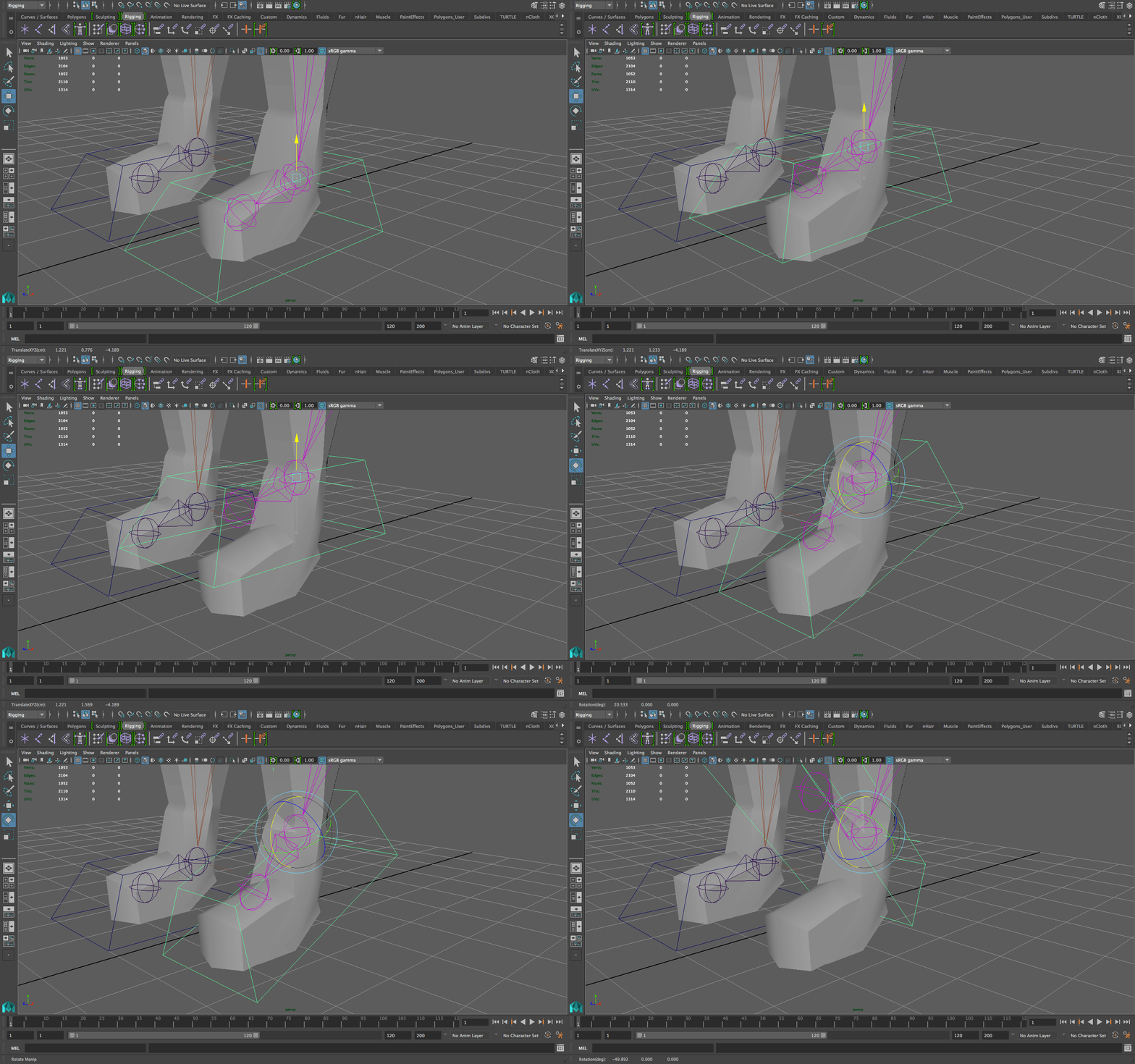
-
Do the same for the other three feet: orient constrain the controllers to the feet joints (not the very final tip, just the foot joint) and parent the ik handles to the controllers.
CREATING AND ATTACHING A CONTROLLER FOR THE HEAD
This is even easier than the feet because it’s one less step: there’s no need to parent an ik handle to the head controller.
-
It’s essentially the same process. Create a custom controller (you can start by making a circle or making EP lines like we made for the back feet box controllers.) Place the controller at the head, match its pivot to the head joint, alter the controller’s shape as needed, freeze transformations, delete history, and rename appropriately.
-
Then, select the controller, and then shift select the head joint, and go to Constrain—>Orient.
-
This is what the head controller looks like for me. The joint where the pivot is the same joint that it’s orient constrained to:
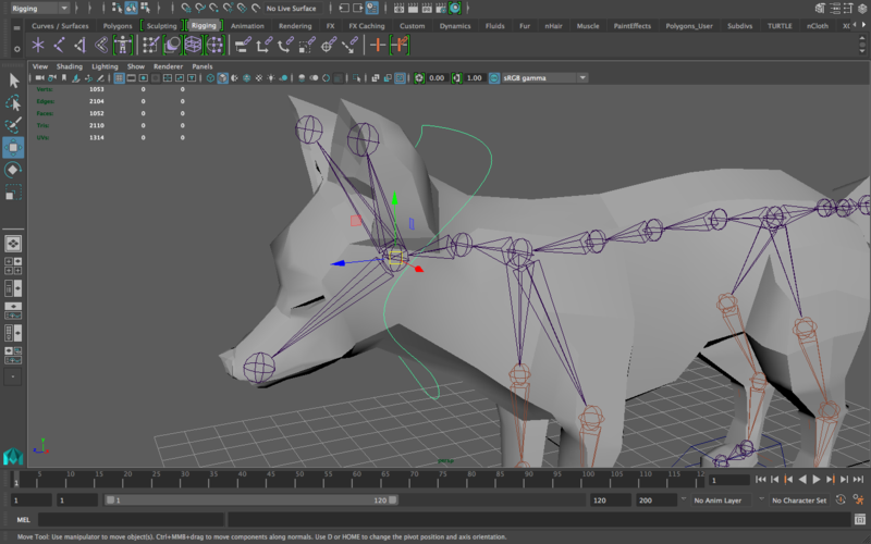
CREATING CUSTOM LOCATORS FOR THE IK HANDLES
One thing you’ve probably noticed as you move the feet controllers is that the “knee” or “elbow” of the four legs moves along, but you have no control over where it points. This is where the pole vector constraints come in. If you remember rigging, then you remember “locators” we’d place behind the legs to be able to point the knee’s direction (or in front of the legs if it was a human/biped). This is the process we are going to do now.
What we USED to do was creating locators, which are these:
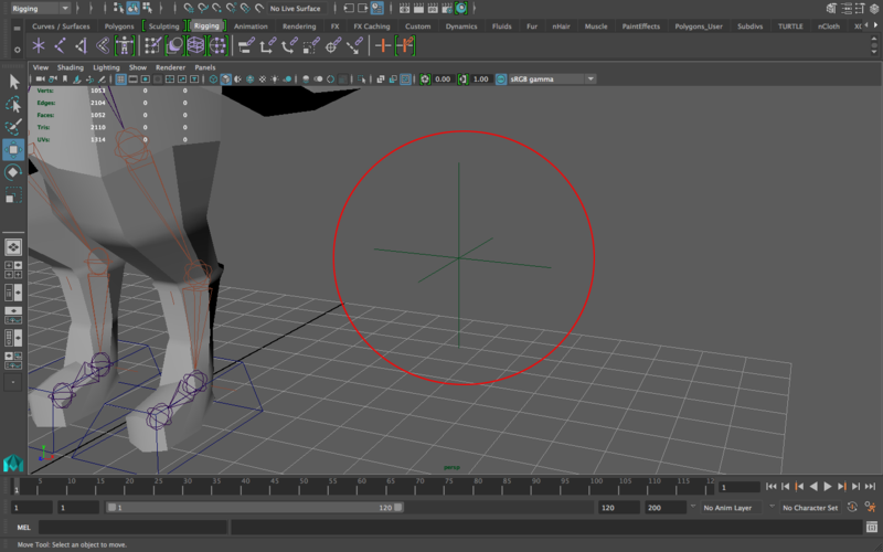
You can find these by going to create—>locator.
If there is a less visible, more annoyingly resistant-to-selection object in Maya than a locator, I do not know of it. I hate these. If you’ve ever animated you’ll know that spending ten seconds looking for these inside the stomach of your character because they were parented to the feet controllers and the feet happened to be rotated and you need them to be far away in the shot you’re working on and you can’t find them and when you finally do you click and you accidentally click the mesh instead and then you try again and you fail and it sucks and AAAAAAAA you suddenly hate animation. These suck. They really do. They’re lines, so they’re difficult to select, and their color doesn’t help. In fact, if you make them bigger and then freeze transformations, they will get smaller again! Because Maya.
Here’s what you should do instead:
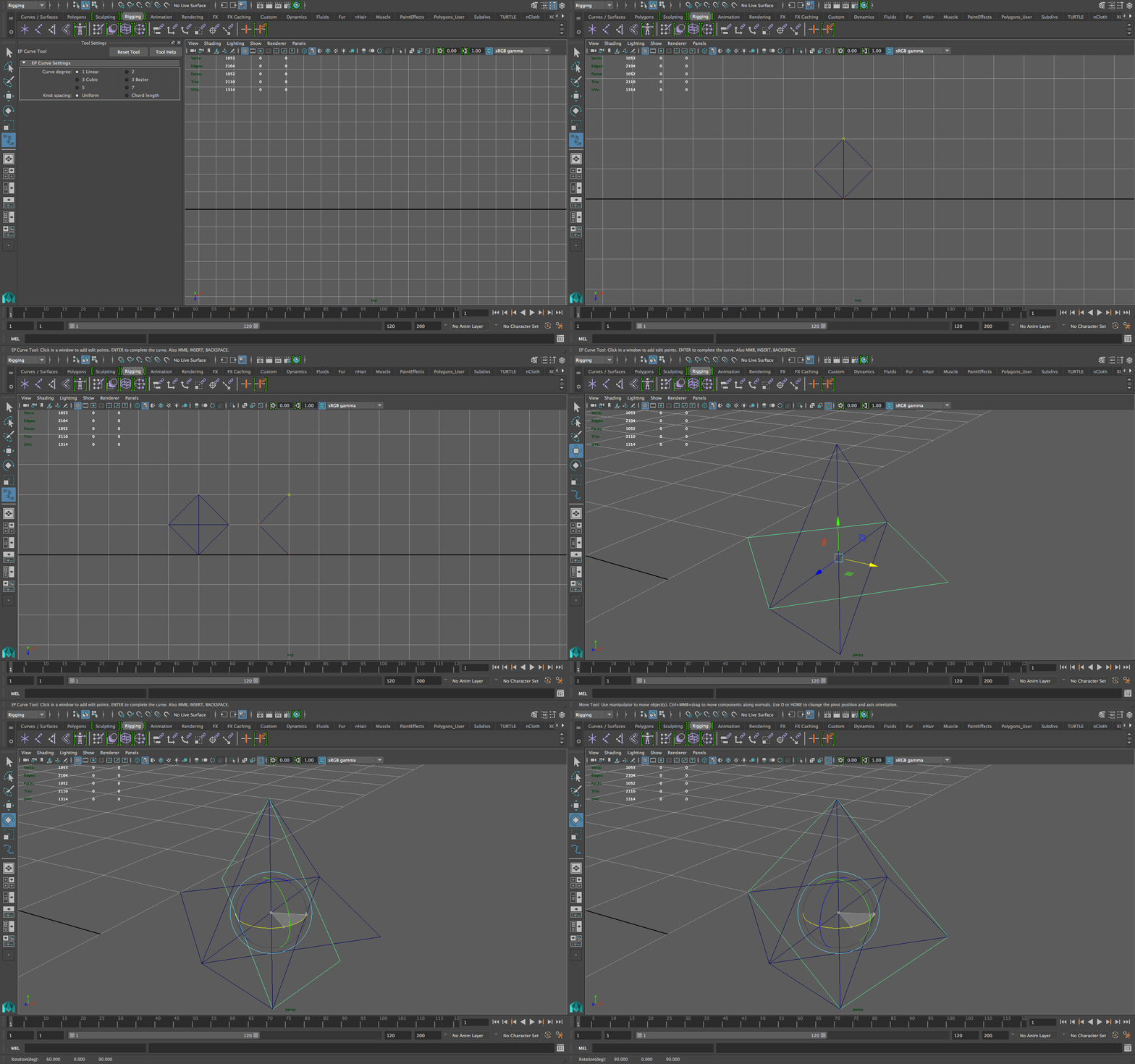
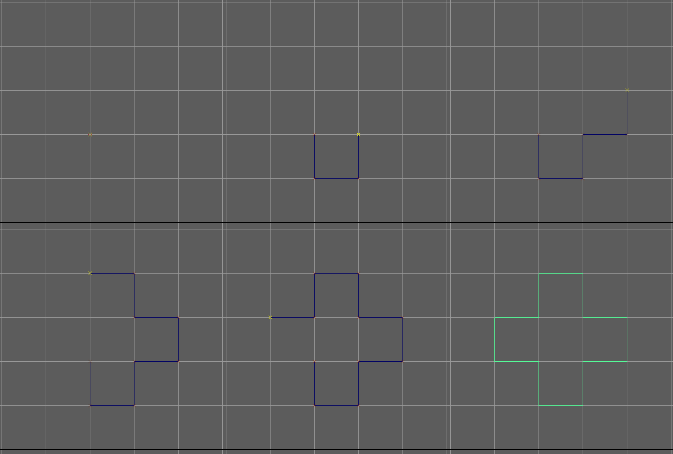
- Just like you custom-made controllers, custom-make a locator you can use for pointing the knees. One rig I downloaded online had diamonds for locators, and I LOVED using it because they were so easy to find and select. So for this example, I’m going to make a diamond. You can choose to follow with this shape or you can make something simpler if you like (as long as it’s not 2d though and not tiny). I recommend following along with this gif though, since I’m going to be doing some line connections with Nurbs, and you might want to have that experience just so you know what you’re dealing with when you’re trying to connect curves. Here’s the process of making the diamond:
-
The final step of the diamond I made in the gif was selecting that final piece and duplicating it and rotating it. However, when you’re done with that, you’ll find that you still have separate pieces. Unfortunately, Nurbs are nowhere near as simple as polys when it comes to connecting vertices/combining meshes. So, here’s a bit of a loop around connecting these: Select all the curves, and then, under the modeling menu, go to Curves—>Detach. This breaks down every line segment into its own curve.
The reason we want this is because Maya treats curves kind of like vectors: the end point of one needs to be the beginning point of the next one if you were to connect them. Doing this with separate lines will be a lot easier. I spent way too much time trying to connect them as they are and the end result always chops off a line. -
Freeze transformations on all the curves and then delete history. Also, center the pivot (select all the curves and go to Modify—>Center Pivot).
-
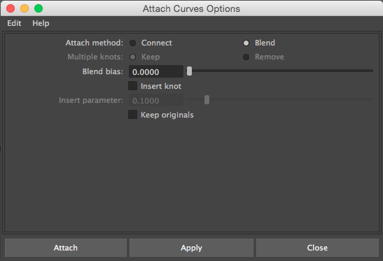
Once you do that, select all the curves, and then go to Curves—>Attach and click the options box. Make sure you have these options:
-
Now it should hopefully be one curve/object. I can resize it (and it won’t get smaller when I freeze transform!), color it, customize it in any way I want. The important point, however, is that you now have a much more selectable, animator-friendly locator than the standard Maya locator.
-
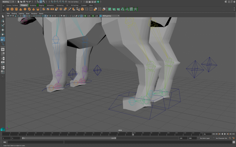
Place the locators behind the “knees” of the legs of the fox. In humans, you’d want them to be in front of the knees because human knees bend forward. For human elbows, you’d put them behind the elbows because they bend backward.
Use the orthographic view to match up the position of the locator to the knee joint. Do this by holding “v” and moving the locator to the exact middle point of the knee joint. Then go into persp when you’re done, and if the locators are too close to the knees, move them backward. -
Duplicate the locator to the three other legs and do the same thing. Then freeze transformations on all of them, delete their history, and rename them appropriately.
-
Now, to apply the locator’s effect, select a locator, and then select its corresponding IK handle (the one it should affect) and then go to Constrain—>Pole Vector. Do this for the three other locators and IK handles as well.
-
Now when you move up a foot, move around the locator and you will see how that gives you the ability to point the knee however you want.
-
This is what my locators look like:
This is the end of the section for Week 1. Submit your fox file with its custom controllers and locators onto bcourses and you will resume from the next section for next week.
IK SPLINE FOR THE FOX’S SPINE (Week 2)
This is the start of the section for Week 2:
This is where things get interesting and a bit more advanced. If you’ve done rigging before, maybe the only new things you’ve seen so far are the custom controllers/locators, but this is where there’s a clear division between a basic rig and more advanced one. Hold on, take your time, and carefully read through the instructions to understand what we’re doing here.
Before I begin this section, I think it’d be good to give a general picture of what we’re doing here. In this section, we’re going to be creating a spline for the fox’s spine. A good way to think of a spine is to think of it like an elastic string. This string has a start and end point, kind of like anchors that serve to hold the string in place. The movement we’re going for would be the equivalent of pulling/pushing on several points on the string.
Now imagine that string being a chain of joints: a spine. That’s exactly what we’re going to do. We’re not going to be moving joints in isolation, the goal is to, when you’re done, be able to move a part of the spline up, and the rest of the joints will curve upward as if you’re pulling the middle part of a string.
This will all be clearer as we proceed.
-
Under the Rigging menu, go to Skeleton—>Create IK Spline Handle and click the options box. In the spline handle settings, uncheck the “auto parent curve.” We’re unchecking this because we’ll actually need to directly interact with this curve a few times, and auto-parenting it to the IK handle will not allow us to do that.
-
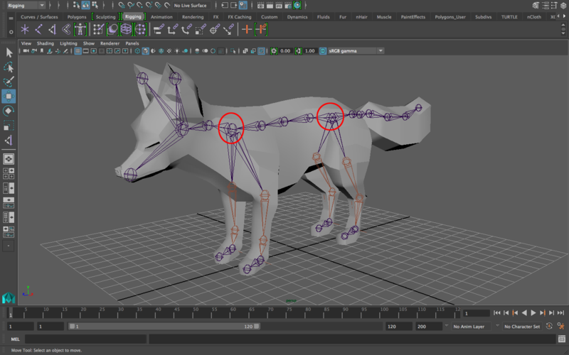
With the IK Spline Handle tool selected, select the root (hip) joint and then select the shoulder joint (the joint between the “shoulders” of the front legs). If you have missed Week 1 Rigging lab, make sure that you have rerooted your skeleton so that your hip joint is the root joint. What you’ve created now isn’t a standard IK handle, it’s actually a spline. If you go into wireframe mode, you’ll see the IK Spline handle (the locator-like object near the shoulder) and you’ll also see a curve before it. That curve is the spline (the string in the analogy I used above). In the outliner, rename the curve created as “spline_curve”. Just for reference, these are the two joints you should select:
-
The interesting part of the Ik Spline handle is this: select it in the outliner and then look at the channel box. Do you see the “roll” and “twist” channels?
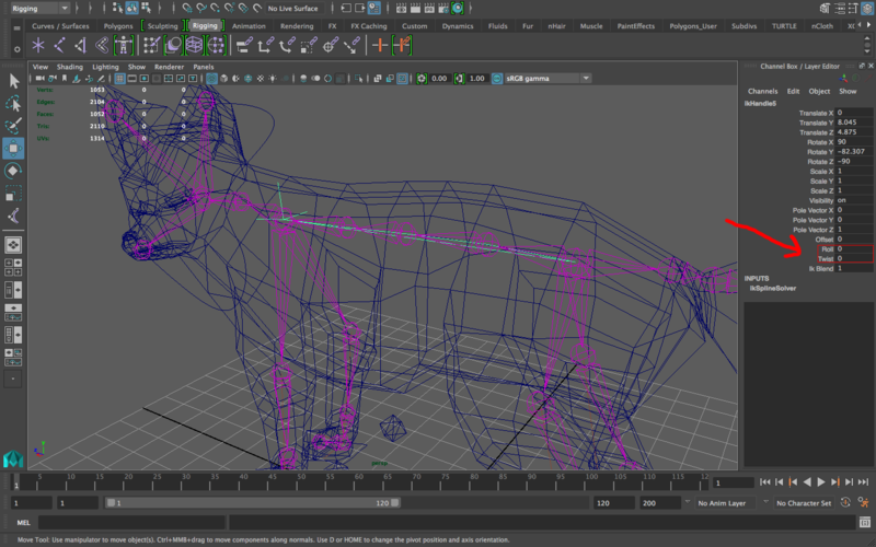
Try altering those (by the way, you don’t need to be constantly putting numbers to see it in several positions, just click on the channel name itself “roll” or “twist” NOT the numbers box and middle mouse drag left and right on the viewport. You’ll see the number increasing/decreasing. Middle mouse dragging to the right increases it, middle mouse dragging to the left decreases it.)
Here’s what altering them looks like:
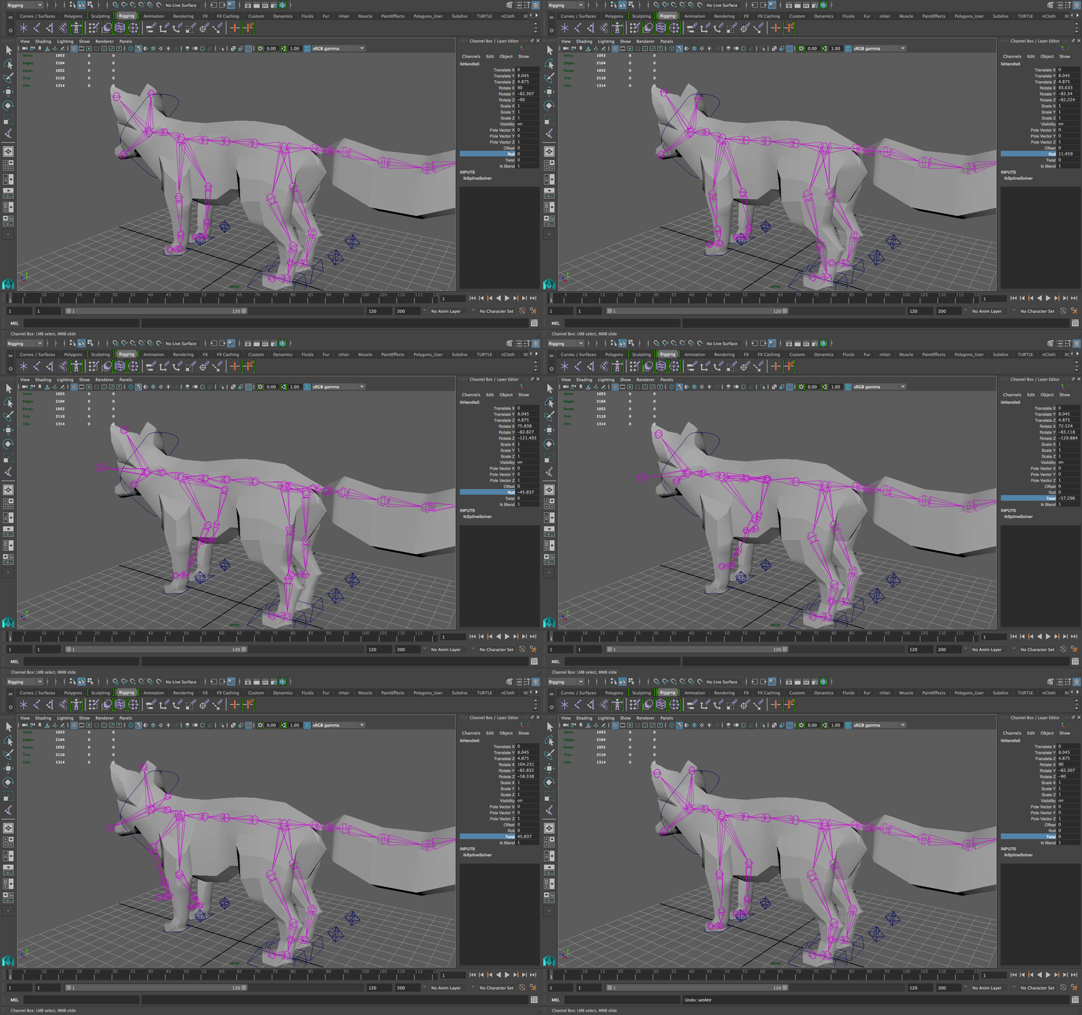
Notice how the “roll” option rolls the whole root (and as a result the whole rig) while the twist just turns the front part of the rig (the second joint you clicked when you first made the spline). We’re only a few steps into the advanced side and you already have way more motion possible with your rig! However, no animator is going to want to go into the channels and keyframe from there. Again, we’ll need controllers. -
Make sure the roll and twist attributes are back at 0. We’re now going to make controllers for the twist and roll. Let’s start with the roll. Make a controller (starting with a circle works well here, but if you want to make a box around the hip, that works too) and place it around the root/hip joint. My controller looks like this:
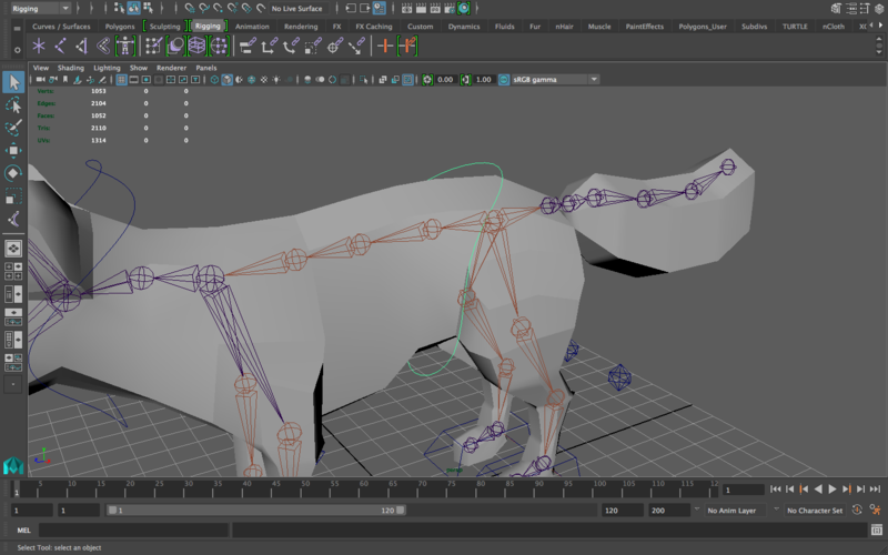
As always, run through the list of things you need to do: match its pivot to the root joint, freeze transformations, delete history, and name it accordingly. -
Create a controller for the shoulder joint. Mine looks like this:
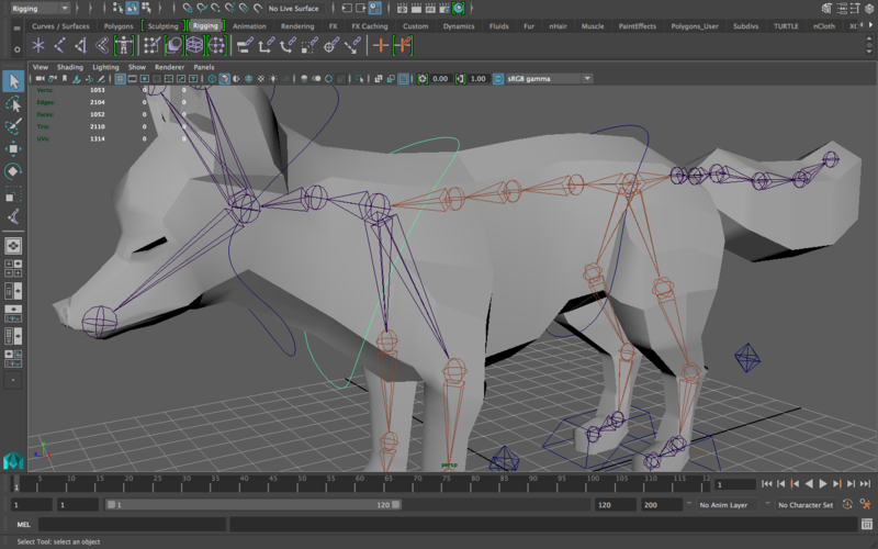
Match pivot to the shoulder, freeze transformations, delete history, and rename the controller. -
This is where things get even more interesting. We’re going to use an editor you’ve probably never used before. It’s the Connection Editor. Go to Windows—>General Editors—>Connection Editor. When it opens, don’t panic.
-
The primary purpose of the connection editor is to relate/link/connect two channels/attributes from two separate objects. If you keep that in mind, none of this should be confusing. The goal here is the following: when you rotate the hip controller, you want the “roll” attribute to change accordingly with it. Let’s get more specific: when you rotate the hip controller in the z-axis, you want the roll attribute to increase and decrease accordingly. The connection editor will allow us to do this.
-
There are two halves to the connection editor: what you’re connecting from and what you’re connecting to. Select the hip controller, and in the connection editor, in the left column, click the “reload left” button. Then, select the IK Spline handle from the outliner, and in the connection editor, select the “reload right” button.
-
Now what you have are the attributes of both the controller and the IK handle loaded side by side.
-
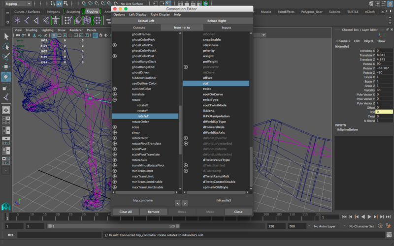
What you want to do is link the “Rotate z” of the controller to the roll attribute. So, scroll down on the left column until you find a “rotate” button. Click on the + to its left to expand it, and it should show three sub-items: rotateX, rotateY, and rotateZ. Select the rotateZ button. It’ll get highlighted and that’s it for the left column. Scroll down in the right column until you find a “roll” attribute and select it. Now the rotate z of the hip controller and the roll attribute of the IK Spline handle are linked like this:
-
Now when you rotate the hip controller in the z direction, you’re going to find that the “roll” attribute in the IK Spline handle is changing. The “roll” attribute will be highlighted in yellow as well, indicating that it’s connected to an attribute in another object (in this case, the rotate z of the controller).
-
Let’s do the same with the shoulders controller, except that we want to link it to the twist attribute, not the roll attribute. So, open the connection editor, select the shoulder controller, and click on the “reload left” button above the left column. Then, select the IK Spline handle from the outliner again, and select “reload right” button above the right column. Select the “rotate z” of the shoulder controller like we did with the hip controller, and then select the “twist” button in the right controller. Now these are connected.
-
Now you have controllers that enable you to roll and twist your rig. Lovely. Let’s move on and add controllers that’ll help accentuate squash and stretch for the rig. So, I explained previously that the spline is a like a string attached to two ends, and that the goal of having it is that you can pull different parts of it, right? That’s what we’re going to do now.
We want to pull parts of the spline, not the whole thing. Therefore, we need to split the string up into parts. This process is called “clustering” and you’ll be moving around clusters to affect specific parts of the spline. -
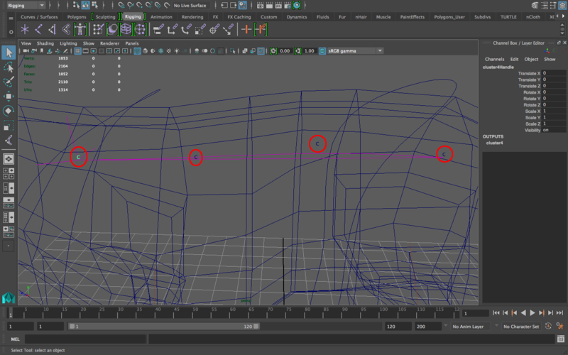
Find the IK Spline handle’s curve in the outliner (the one you named spline_curve). With that curve selected, go to Select—> Cluster Curve. You’ll find several “c” letters created on the curve, one at each joint. If you select one of these and move them, you’ll find that they move the joints around them, exactly like pulling a string or pulling on a joint chain. This gives you a MASSIVE range of motion for your animation that is incredibly useful in having advanced animations. This is what these look like:
-
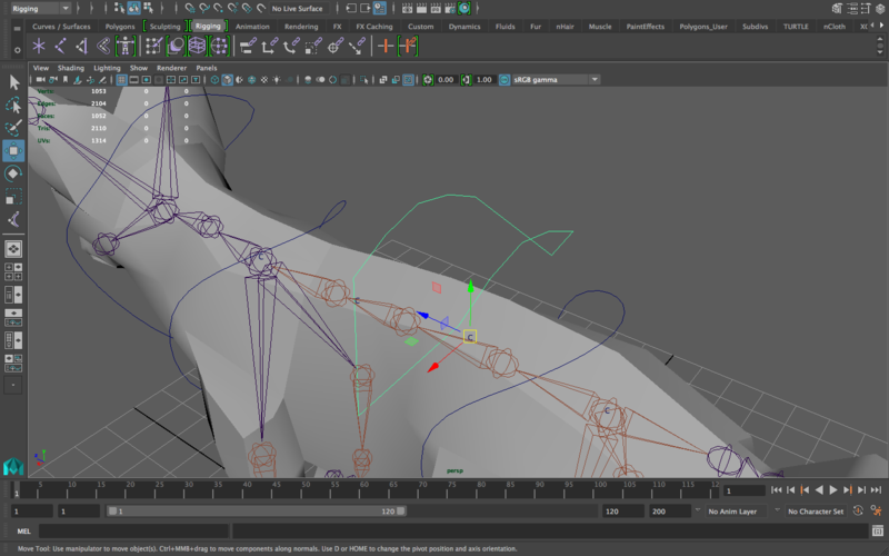
Obviously, selecting the “c” letters wasn’t very easy if you tried to move them. You probably had to zoom in and click and drag a small box around one to select it, or you selected it from the outliner. As always, when something is hard to directly interact with, we give it controllers that are much easier to interact with. So, create one controller for each “c” (just create one curved one and duplicate it once for each “c”). This is mine:
-
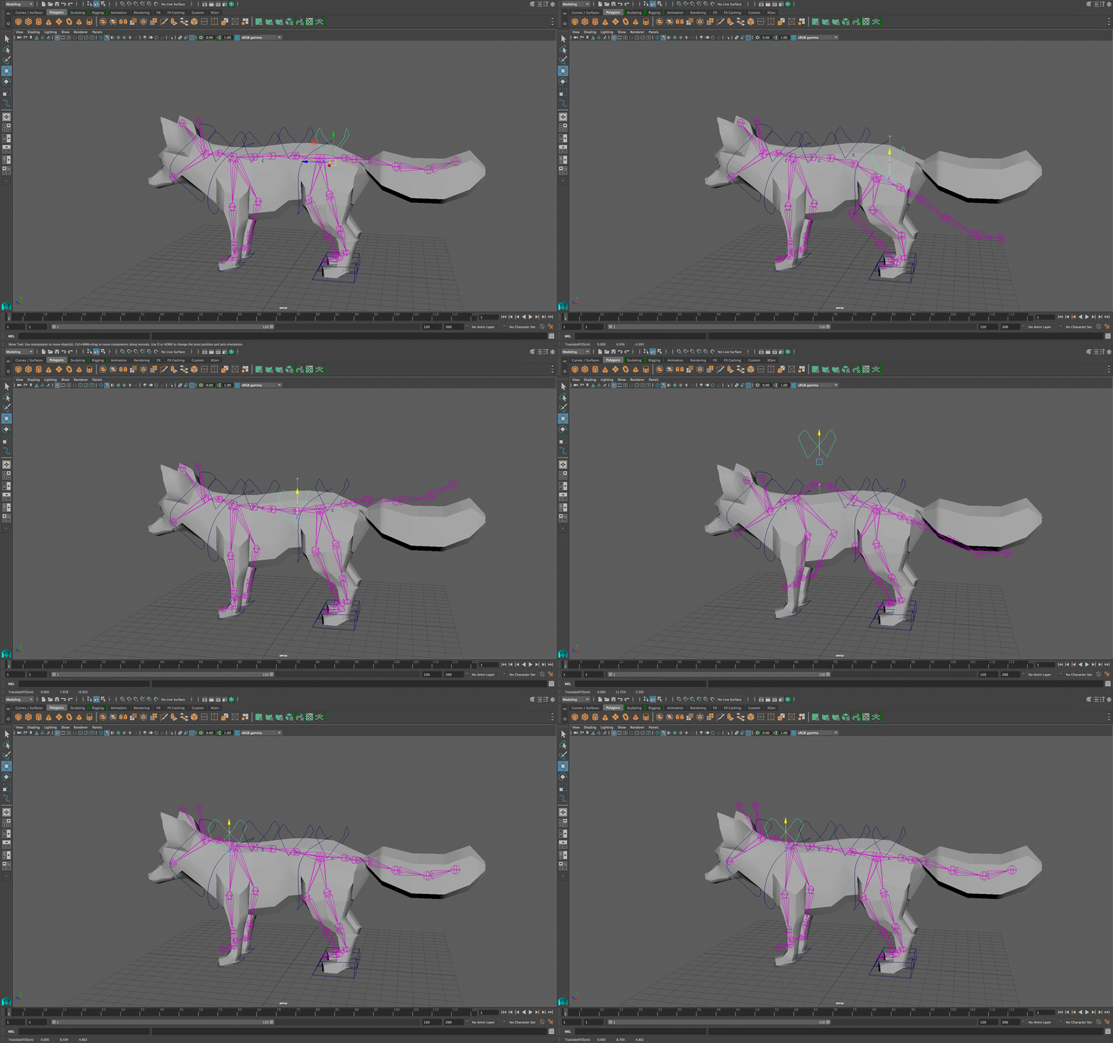
Center the pivot of the controller on the “c” that corresponds to it since that’s what you’re indirectly interacting with. Then, freeze transformations for the controller, delete its history. Now, select the controller first, and then shift select the cluster (the “c”) that corresponds to it, and then do Constrain—> Point and select the option box. Make sure “maintain offset” is checked and then apply. Do the same for the rest of the controllers and their clusters. In the end, when you move one of the controllers, it should look something like this:
-
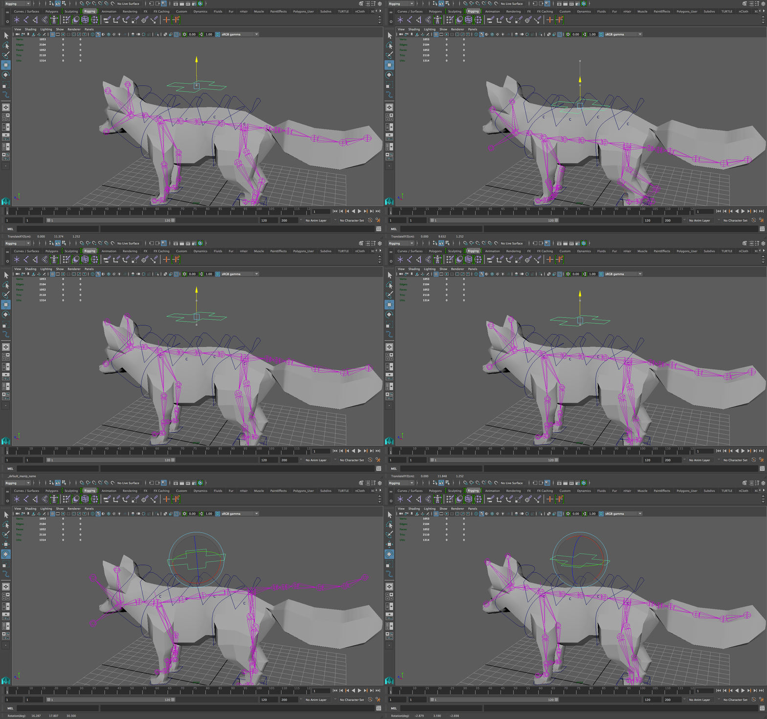
Once every cluster has a controller, you’re good to go for the spline. The next order of business is a center-of-gravity controller. Create a controller that either goes all the way around the middle of the fox, or exists above the fox. For me, I’m going to make a plus-sign controller that should be identifiable enough and I’m going to place it above the fox. This is what my controller looks like:
-
Select the spline_curve and then shift-select the CoG (center of gravity) controller and then press “p” to parent. Now when you move the CoG controller, you can see the whole body of the fox moves, except for its feet positions. This is essential to getting good squash and stretch, and for really accentuating walking/running/jumping/landing or basically any physical action where you can emphasize gravity’s effect on the fox. This is what moving the CoG controller around looks like:
RIGGING THE TAIL
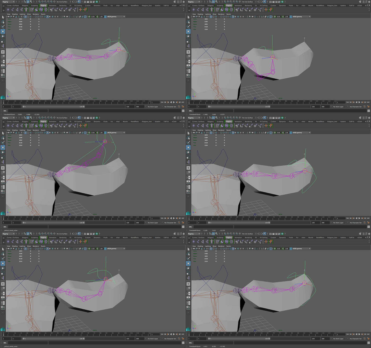
- I’m going to leave this one up to you: either make it an FK rig, an IK rig, or an IK Spline based on what you’ve learned so far.
- Create custom controller(s) depending on which rig you chose to make.
- I chose to make it an IK rig and here’s what it looks like:
CLEANING UP
-
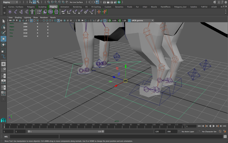
Now we have a bunch of controllers everywhere. If you want to move the whole fox, it’s going to be a nightmare. We need a master controller that controls everything. Again, as a beginner you’re probably used to seeing one big circle for the master controller but that’s a little inconvenient and you aren’t a beginner anymore. It’s nice to get in the habit of having more specific, easy to read controllers. For that purpose, many professional rigs use master controllers that are made to look like arrows, constantly reminding the animator of where the rig is pointing.
Reminding the animator where it’s pointing? Can’t the animator just see that? Sometimes not! There are certain scenes where an animator may choose to animate the fox turning around, and can do so by turning the spine, and then the tail and head, and then the feet, etc. without ever turning the master controller (depending on the requirements of the shot). Therefore, an animator can end up with a position where the “forward” direction of the master controller is almost 180 degrees the opposite of the “forward” direction of the character’s body. Having a perfect circle as a controller, or any shape that doesn’t indicate directionality for that matter, wouldn’t help in a situation like that. That’s why an arrow is ideal. -
Use an EP curve, make sure it has the “1 Linear” option selected, and create an arrow that’s big enough to be about the same size as the character’s body. Here’s what mine looks like:
-
Rename it as master_controller, freeze its transformations, and then delete its history.
-
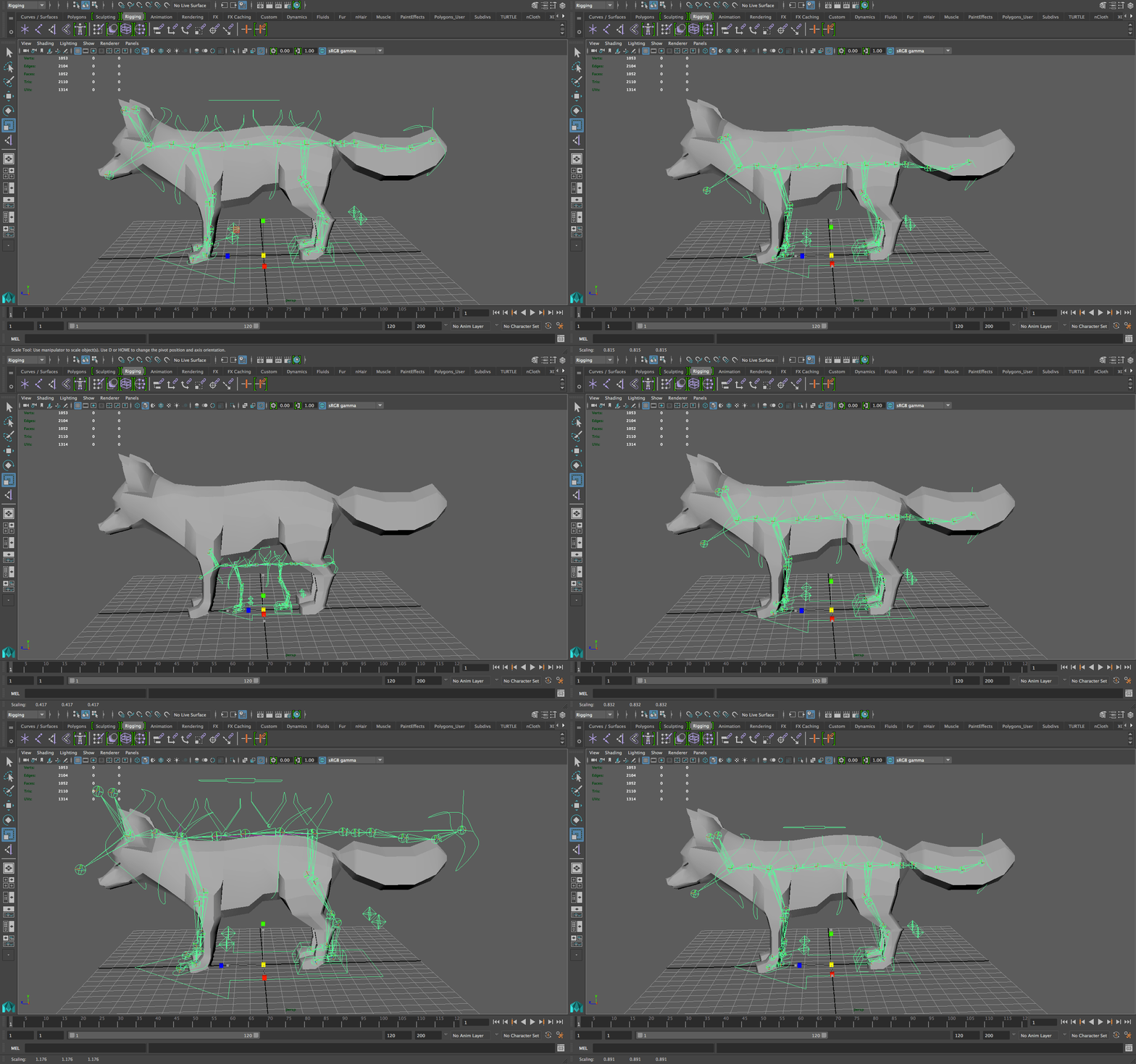
It’s not a master controller if it doesn’t control everything! So, I’m going to parent everything to the master controller. Everything in the outliner that isn’t the fox model itself—drag it under the master_controller. To test if this has worked, resize the master controller up and down, everything should be resizing in proportion. If something is not resizing in proportion (i.e. changing weirdly when you resize) then you probably forgot to parent some component of the rig to the master controller. Here’s the indication that the master controller parenting was a success:
-
Okay, other than the master controller, let’s restrict motion where it’s needed. Go to the hip controller, select the Translate X, Y, and Z channels of it in the channel box. Hold right click on them and select the “lock selected” button. Now, if you go to the move tool, the arrows will be grayed out—you can’t move this controller anymore (unless you unlock these attributes). Do this for every controller: what motion do they not need? Lock the channels they don’t need.
Why do we do this? This is an essential part of rigging because this is considered to be the communication between the person rigging and the person animating. If I open your rig, it should easily spell out for me which motions are allowed and which ones aren’t. I should NOT be able to move around the head, I should only be able to rotate it. If I accidentally go into the move tool and see that it’s open, that means I’m allowed to move it (implying that you rigged it in a way where that motion is possible). Then when I do move it and realize it doesn’t look any good (i.e. it wasn’t rigged to move) then I’m distracted and I don’t know what range of motion this rig was meant to have. Therefore, you should only allow motion where it should be allowed—don’t leave things open “just in case” an animator needs that range of motion. That way, the person rigging is communicating to the animator HOW to use the rig.
One other thing to note: by having an IK Spline handle, you are now capable of switching it from IK to FK at any time! Below the “roll” and “twist” attributes, there is an “IK Blend” channel. If you turn that to 0, the spine won’t behave like a spline anymore, and it’ll be FK again.
And, you’re done! Select the root joint, shift-select the mesh, and go to bind skin (select the option box.) Make sure the binding method is set to “geodesic voxel” and click apply. Now when you move the rig around, the mesh is going to move along with it.
Obviously there’s going to be skinning issues, but we’re not evil enough to make you skin a character that isn’t going to be in your short.
The skinning lab is available as a guide on how to skin your characters for your short. It isn’t an assignment, it just runs through good practices, which options to use, etc.
This is the end of the advanced rigging lab! Submit your fox model onto bcourses with its rig and basic skinning applied.