INTRODUCTION
Part II - Constraints, Controllers, and Skinning
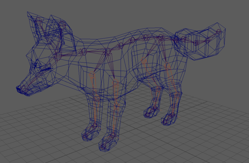
In the first rigging lab, we added a skeleton to a fox model. We’re going to return to that project and make it easier to manipulate those joints and teach the mesh to deform according to how the joints move.
If you’d like, you can also follow alongside this lab with this playlist.
Where we left off:
PARENT CONSTRAINT - FOOT CONTROLLER
Our fox should have a skeleton of oriented joints and IK handles for each of its legs. You might have noticed that the IK handles are a bit tricky to click in the maya window. We’re going to create a controller which is easier to interact with and will drive the IK handle.
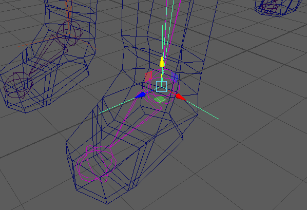
Selecting the IK handle is made even more difficult with the overlap of mesh and joints
For this lab, we’re going to use NURBS curves for our controllers. NURBS are not rendered and will not appear in your final short. They will be visible to your animators when they work in Maya so they can be useful for guidelines and tools. An important principle to rigging is making controllers which convey their purpose through their appearance. While we will be using NURBS circles/ellipses because they are easier to make, students are encouraged to peek at the advanced guides and see how to make controllers with depth and unique shapes. For our IK controller, create a nurbs circle (Create -> NURBS Primitives -> Circle).
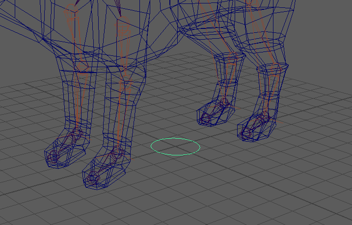
Move and scale your ellipse using orthographic perspectives so that it rests beneath one of the fox’s feet.
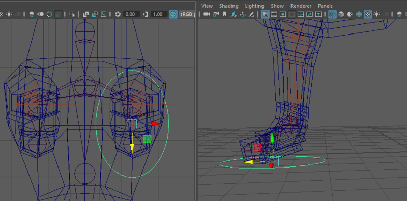
Check the Channel Box info for your ellipse. Because you moved it, there will be some nonzero values here. On a rig, it’s important that zeros represent the default positions. It is absolutely important that every single controller has its transformations frozen before being attached to anything.
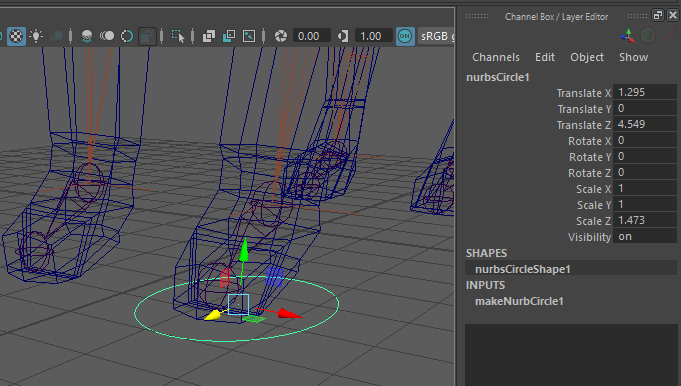
Once you’re happy with the placement, use Modify-> Freeze Transformations to zero-out your channel box.
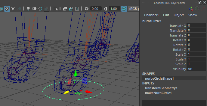
Now might be a good time to name your controller (I named mine LFrontLeg_CON) and delete its history if you haven’t already done so.
Now, if you’ve been animating the foot, you can always return it to its default position by entering zeros back in the channel box. The next step is to attach the controller to the IK Handle through “P” parenting. In modeling, we created a hierarchy of objects which followed each other by selecting the child object, then the parent, and pressing the “P” key.
Why are we using “P” parenting and not a parent constraint? “P” parenting changes the hierarchy in our outliner and nests the child under the parent. We can’t do this for joints because joints are already arranged in a hierarchy. “P” parenting the joints again would mess up their hierarchy.
However, IK handles actually live outside the joint hierarchy. You can see this in your outliner. LFrontLeg (my IK Handle) is not nested under cog (my root joint).
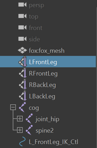
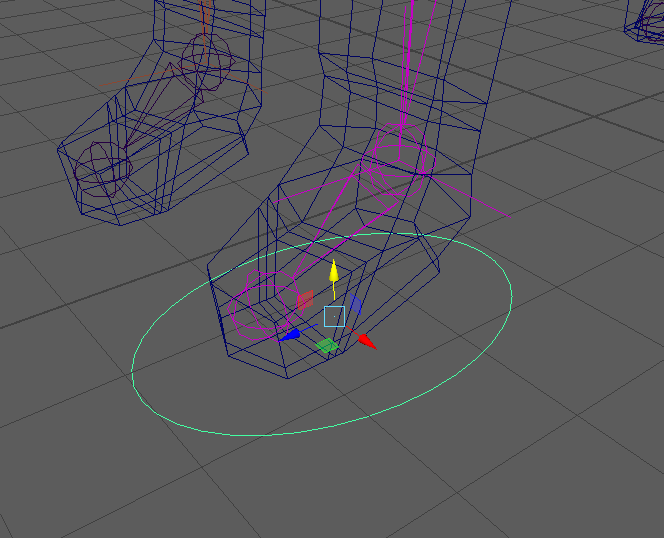
Select the child object (the IK handle), then the parent (your NURBS circle controller), and press the “P” key.
Now that the controller is parented, selecting just the controller should also select the corresponding IK handle. Using the move tool with the controller should now move the IK handle and flex the knee joint. You’ll also notice that the IK handle is now under the controller in the outliner. Although we could have achieved similar results with a parent constraint, “P” parenting here gives us more organization in our outliner.
POLE VECTOR CONSTRAINT - KNEE CONTROLLER
As we discussed last week, we don’t have absolute control over where the knee points in an IK handle by default. To do so, we’re going to create another controller that exists as a point in 3D space. Use Create -> Locator.
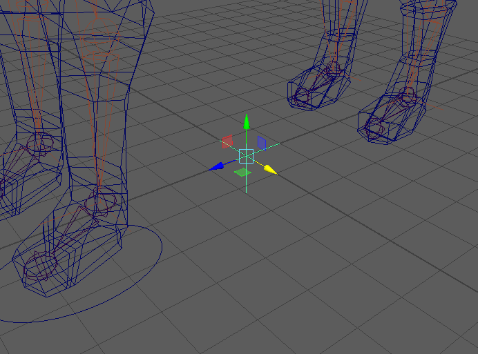
We’re going to want to place this locator behind the leg at the height of the knee joint. After we apply the constraint, the knee will want to move in the direction of the locator. Because of this, we want to place the locator far enough away that the knee won’t pass over it at maximum flex. NOTE: After testing controllers be sure to put everything back to their default positions before you proceed to later steps.
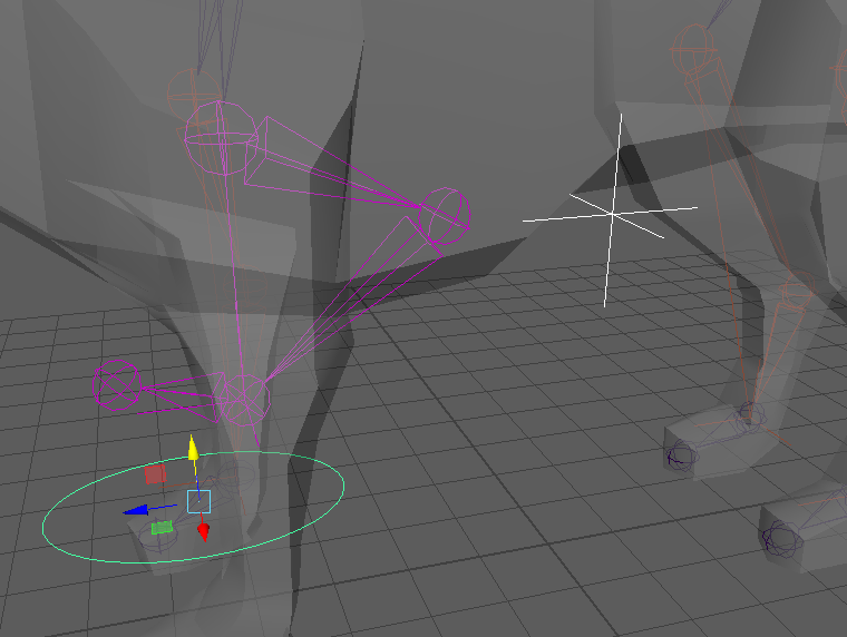
Once the locator is where you want it, F R E E Z E - T R A N S F O R M A T I O N S. Remember, this needs to be done for every controller before it’s attached. Going back and fixing uncleared channel boxes (either through undo’s or deleting/recreating the controller) can cause additional issues so it’s best to get it right the first time around. After freezing, we’re going to add a Pole Vector constraint to our IK Handle. Generally, constraints work by selecting two entities and linking their transformations in some way. When applying contraints, order of selection matters. Select the “driver” first then select the “driven” second. In this case, our locator drives the IK direction so the locator is the driver and the IK is the driven. After selecting the locator and the IK Handle (NOT the new IK controller) use Constrain -> Pole Vector.
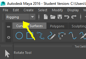
If you’re having trouble clicking the IK Handle, it can be selected from the outliner. If you don’t see the “Constrain” menu, make sure this tab is set to “Rigging.”
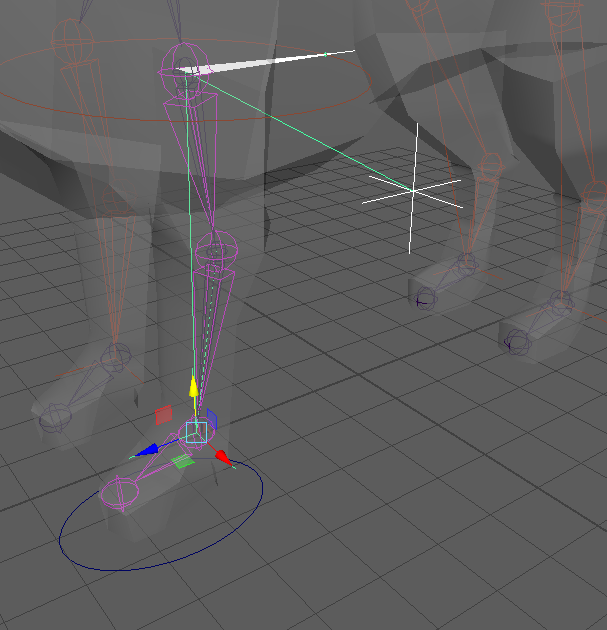
Once linked, there should be a line which links the IK handle and the locator to communicate that they’re now buddies. Test the controller by moving the foot controller upwards to flex the leg. Move the locator side to side to make sure the knee follows its influence.
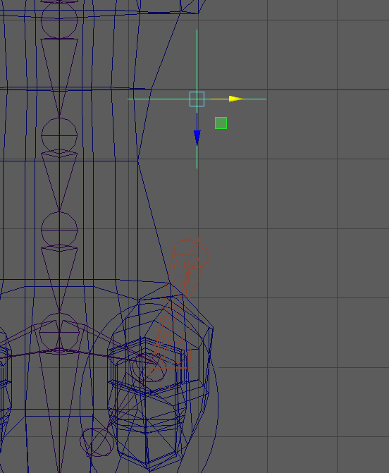
ORIENT CONSTRAINT, SHARED PIVOTS - TOE CONTROLLER
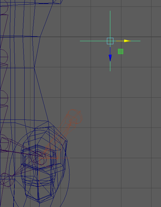
Even with all this control over the leg, you’ve likely noticed that the toe joint seems to point wherever it likes. This calls for another controller. Create a new NURBS circle and move it directly in front of the foot using orthographic views. I squished my ellipse down vertically with the scale tool to help communicate what part of the mesh it controls.
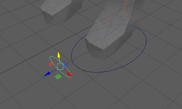
Once the controller is where you want it to be, FREEZE TRANSFORMATIONS. Selecting the controller first and then the ankle joint second use Constrain -> Orient. We’re using the ankle joint because an orient constraint will pass along rotations. Rotating the toe joint will just cause it to spin in place. Rotating the parent, the ankle joint, the toe will move around relative to the rotation.
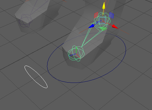
Testing your controller will reveal that rotating this controller will move the toe joint. Note that this controller will work with rotations while the foot controller works with IK’s and prefers translations/movements. Distinguishing these differences to your animator is valuable and we’ll discuss ways you can do that at the end of the lab.
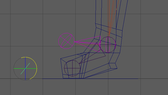
One downside to our current toe controller is that it gets left behind as the toe rotates away. To fix this, we’re going to move the pivot of our toe controller. Pressing “D” while selecting your controller will allow you to move the pivot.
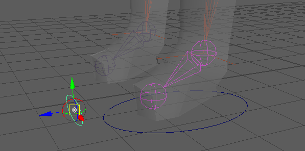
Pivot mode: Note the white circle at the center
In order to make sure that the controller pivot is the same as the joint we’re going to use snap mode. Pressing “V” will toggle into snap mode. Now the pivot should pop around as you move it, trying to snap to significant points. One of those points should be the ankle joint. Double check that it is centered in the joint using orthographic views.
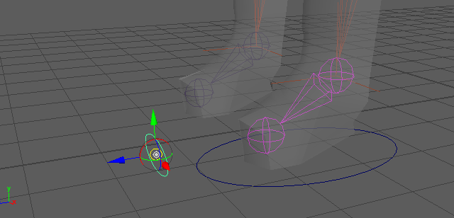
Snap Mode: Note that the yellow square becomes a ring
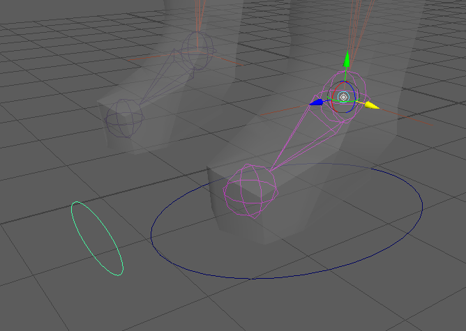
Rotating the controller now should cause it to swing along with the toe.
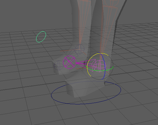
Great job! Now do everything 3 more times to rig each leg. Yay quadrupeds! You can duplicate your existing controllers and move them over so they match. Just remember to FREEZE TRANSFORMATIONSSSSS
AIM CONSTRAINT - EYE/LOOK CONTROLLER
Aim constraints rotate the driven object so that it is oriented towards a target (driver). These are very useful constraints but, alas, our fox lacks eyeballs to rig. I whipped some up for us to use. I think they illustrate how helpful it is to have eye sockets on your mesh. Download and import eyes.ma to your scene. A black-and-white eye texture may be applied to the eyeballs automatically. If it is not, assign each eyeball a Lambert shader (right click -> Assign New Material -> Lambert), attach a file to the Color attribute (click checker box -> File) and load pSphereShape1_color.iff into the “Image Name” field.
(!info)
Reminder: in this class, we use PxrSurfaces to shade objects for our final renders, since these are compatible with RenderMan. Other materials, like Lambert shaders, should only be used for visualizations in the viewport.
Import the file into Maya and we can proceed with learning aim constraints.
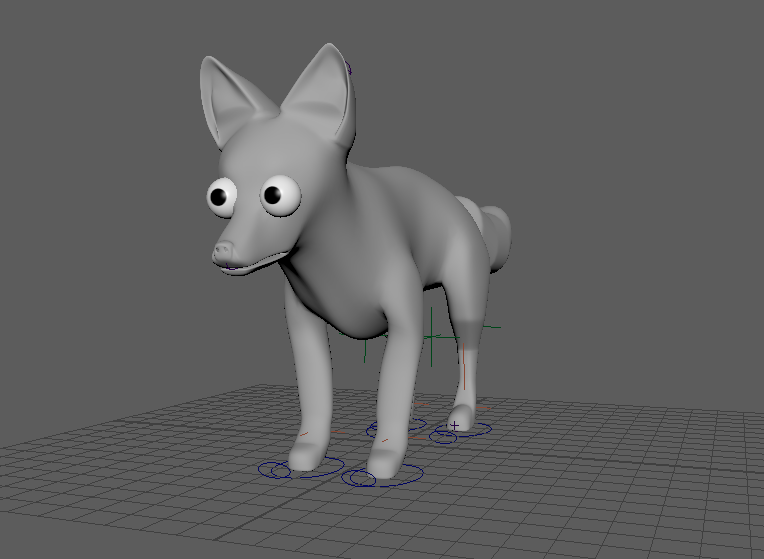
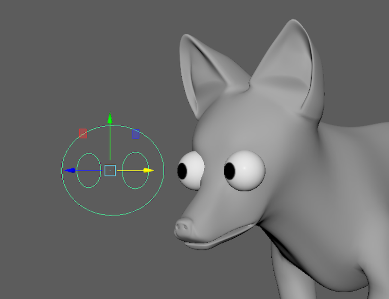
It looks a bit surprised.
Create a pair of NURBS circles and position them in front of the eyes. Use orthographic views so make sure they line up properly.
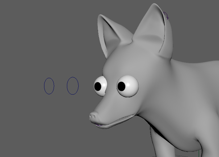
Say it with me now: freeze transformations! When working on your personal models, make sure the eyes are frozen too. Select a controller then the corresponding eye and use Constrain -> Aim Constrain. Repeat for the other eye. The fox is now suspicious of the controllers and will try its best to watch them at all times. Move the controllers around and test things.
(!info)
if the eyeballs flip around or stare off at a weird angle as soon as you apply the aim constraint, click on the Aim Constraint option box and check the “Maintain offset” checkbox.

While moving them separately can look fun and silly, it would be useful to have a way to move them both at the same time. Our controllers will need controllers. Create a new NURBS circle and line it up with our two eye controllers.
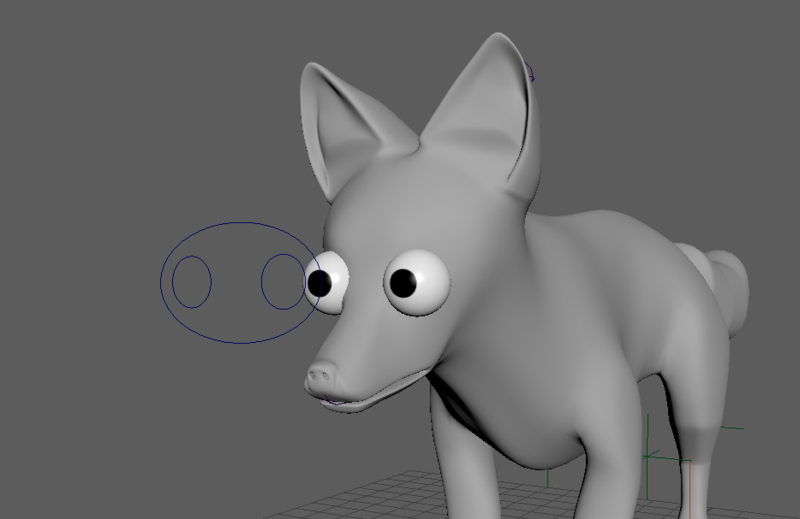
To make things work properly we’re going to need to use the parenting tool we used when modeling. When using “P” parenting, remember to Child -> Parent which is pretty much the opposite of what we’ve been doing for operations in the Constraint menu (i.e. Driver -> Driven). Select a smaller circle, then the larger one and press “P.” Do the same with the other controller. Generally, when linking controllers to each other (rather than joints) we will use this form of parenting because it makes useful hierarchies.
Now that they’re parented, moving the larger controller will also move the smaller controllers.
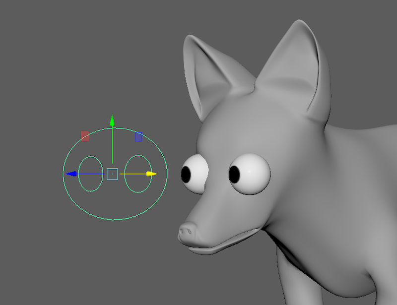
FORWARD KINEMATICS, PARENT CONSTRAINTS (FK) - TAIL CONTROLLERS
We’re going to make an FK rig for our fox tail. This will give us complete control over the rotation of the tail joints and will group them in a hierarchy from base to tip. Start by creating a NURBS circle and using “V” to snap them to the location of the tail joints. Duplicate and shift them down until each joint is accounted for. I scaled by ellipses vertically because I didn’t want them to overlap when the tail swished side to side. Don’t forget to freeze transformations on all of them.
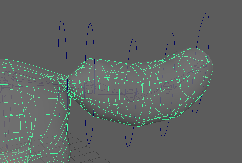
Now Constrain -> Parent each controller to its respective joint. We want to use parent constraints here rather than “P” parenting because these joints already have parents. If you use “P” parenting, a joint will disconnect from the joint that led into it: the joint’s parent.
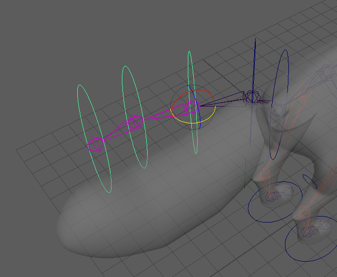
If you try to move the controllers now, they’ll just spin in place. This is because they’ll listen to their parent controller before listening to their parent joint. Since we want to make a hierarchy, we’re going to use the “P” method of parenting rather than using a constraint. Select the second and first controllers (in that order) and press P. The second controller should now obey the rotations of the first. Work your way down the tail linking 3->2, 4->3, etc. until the tail is complete.
MORE PARENTING - CONTROLLER HIERARCHY
There are some final tweaks we need to make before we’re ready to apply the skeleton to the mesh. In the end, all of our controllers will be grouped under a single master controller.
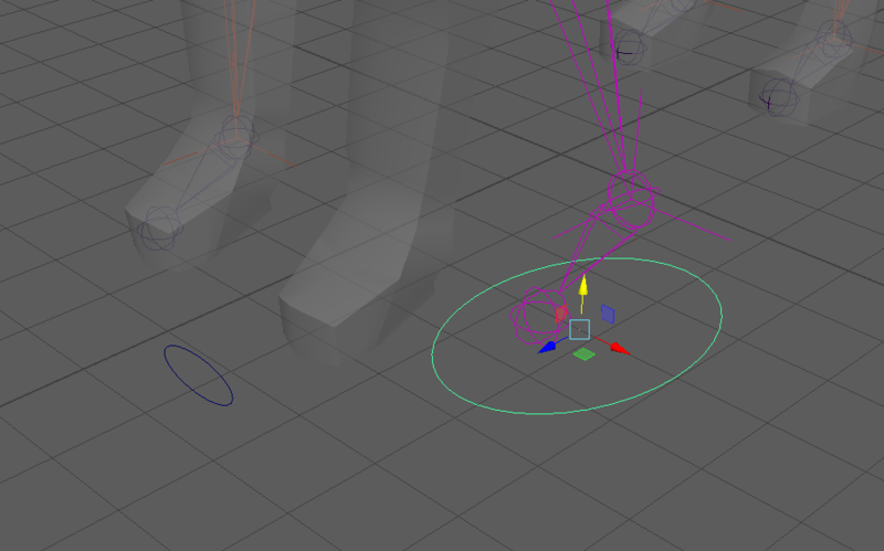
Our first case of adding hierarchy will be with the feet. Since the toe controllers should follow where the feet go, we’re going to parent them to the foot (IK) controller. Do this with each foot.
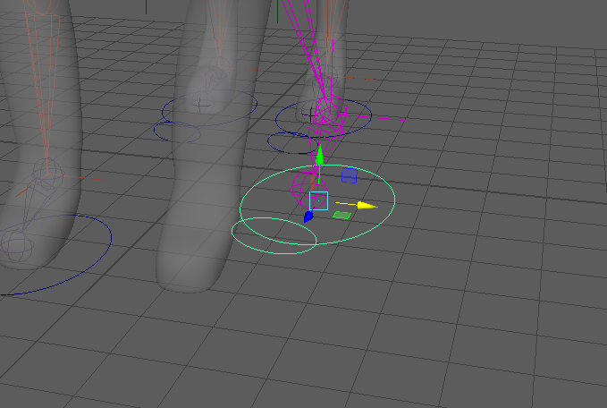
We never actually created a connection between the eyes and the rest of the fox. If the fox were to walk away, the eyes would be left behind. To fix this, we’re going to add a head controller which will also help point the head of our fox. Snap a new NURBS circle to the fox’s head joint. Move and scale it so it’s visible from most angles and doesn’t disappear inside the mesh.
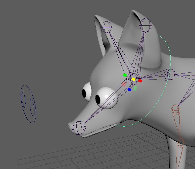
It should looks something like a loose collar.
Now parent each eye and the larger component of the eye controller (one at a time) to the head controller using P. When you move them, the eyes and controller should swivel. The mesh still doesn’t so it might look a bit weird. We’re getting to that step soon.
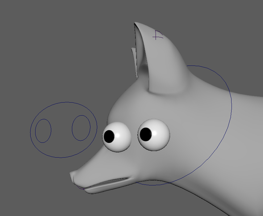
This controller should also move the head. That seems like a reasonable thing for a head controller to do. Since it’s already snapped to the head joint, Constrain -> Orient the two. Make sure to click the driver (controller) first this time. It’s easy to forget since we’ve been “P” parenting for a while. With that done, the head joints should follow along.
Note: if the orient constraint is doing weird things to the head joint, refer to the frequent reminder, given throughout this lab, on how to get controllers ready for use.
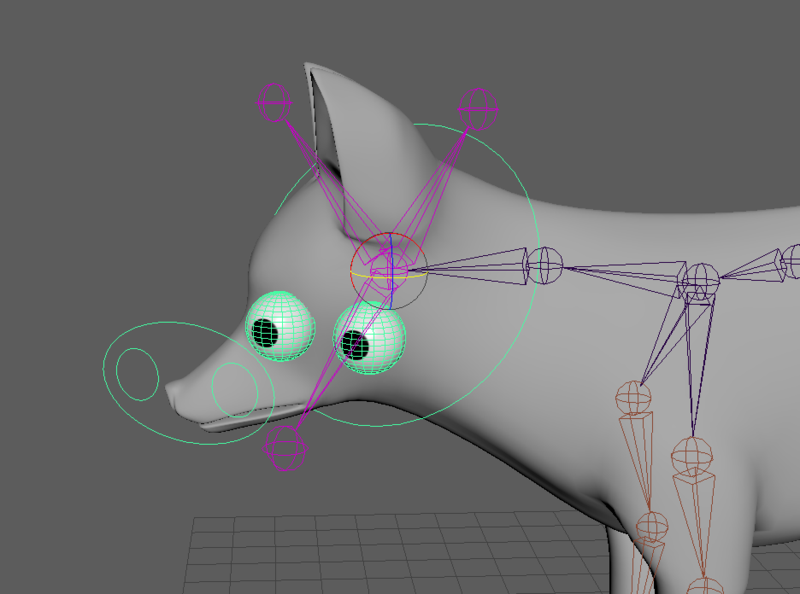
A perfectly normal fox.
Next we’re going to make a Center-of-Gravity (COG) controller. Make a new ellipse and have it wrap around the upper half of the fox.
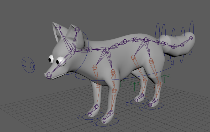
I’m sure you’ve already frozen transformations. Good for you. I didn’t even need to remind you. Using “P” parenting, we’re going to have the COG be the parent of the head controller, root joint*, and the controller for the base of the tail. Parent them one at a time, selecting the COG controller second (because it’s the parent). Since the base of the tail controls all the other tail controllers, your COG controller should pretty much control everything but the locators and your feet. When you move this controller, the fox hunkers down or leans to the side.
*The highest joint in the hierarchy - In this case it’s the joint directly in front of the hips.
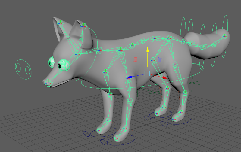
As mentioned above, the only controllers that get left behind are the feet and locators. Create another NURBS circle around the entire fox.
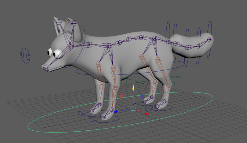
Again, awesome job on remembering to freeze transformations. Making your own rigs will go much smoother now that you’re in the habit of doing that. One by one, parent the foot controllers to the new master controller using P. Since we’re not using the “Constrain” tab, it goes child-> parent or FootController -> MasterController. The master controller will also be the parent of each locator and of our COG controller. After all of those are added, the master controller should select the entire rig.
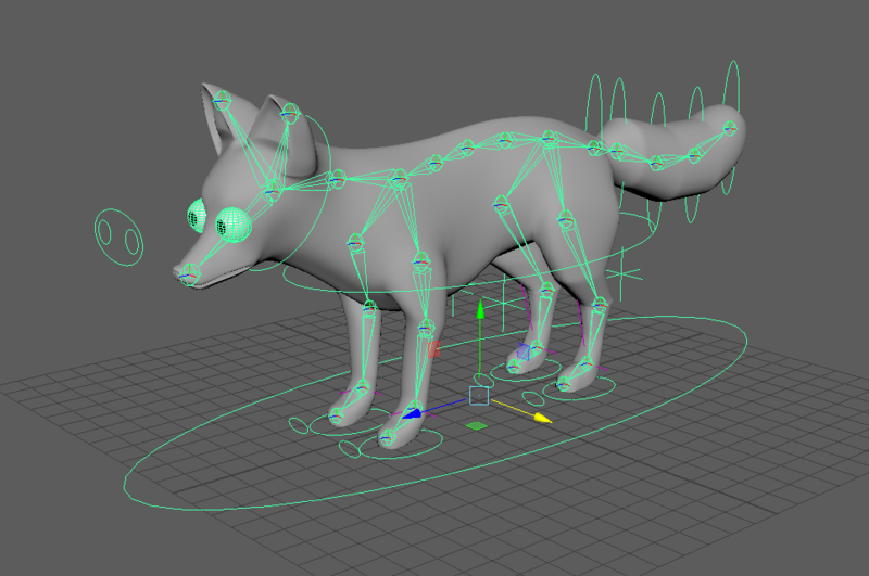
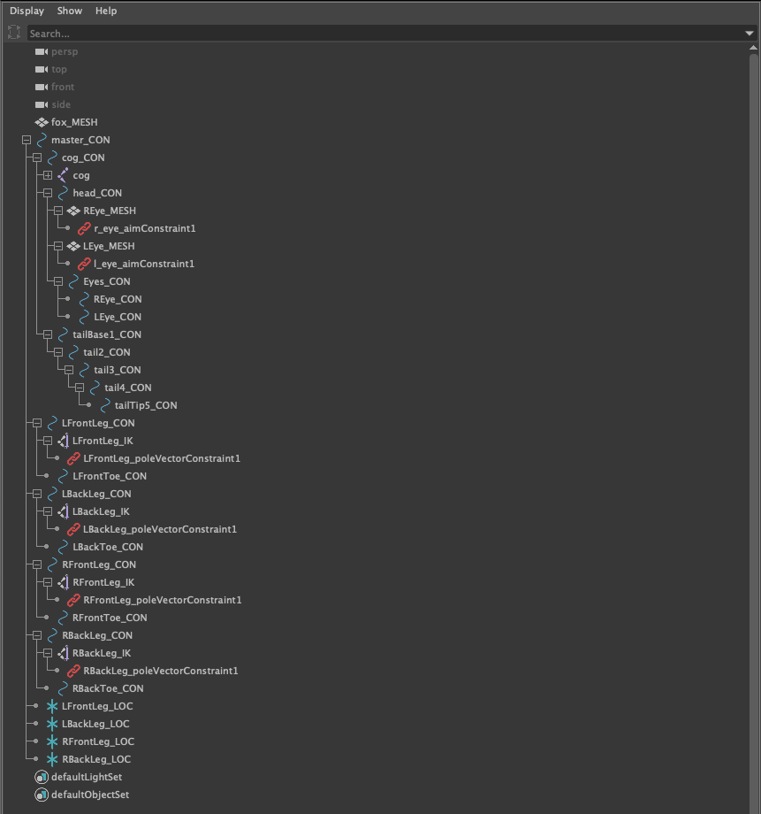
Take a look at my completed outliner and compare it to your own. Note that everything except for the fox mesh is parented under the master controller. If any of your controllers seem to be parented incorrectly, one simple fix is to drag the controller to its correct position in the outliner. To parent objects using the outliner, press and drag the icon next to the object name, then release while hovering over the correct “parent” object. While you don’t need to imitate the particular naming convention I used, do make sure that all of your controllers, joints, IK handles, and locators are named in a way that would be easy for anyone using your rig to follow!
Awesome job! Quadruped rigs are not easy but this example should help you apply controllers to your own characters.
SKINNING
Now that we have a better grasp on how to manipulate our skeleton, we’re going to attach the skeleton to the mesh. Select your root joint and then the body mesh of the fox. Go to Skin -> Bind Skin and click the options box. The dialog should look something like this:
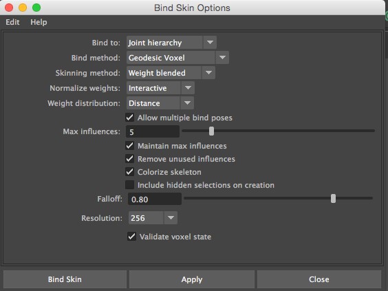
If it doesn’t, change it so it does. Our Skinning Guide provides explanations for each of these options.
Click “Bind Skin” and start playing with your rig to discover why refining your skinning is important.
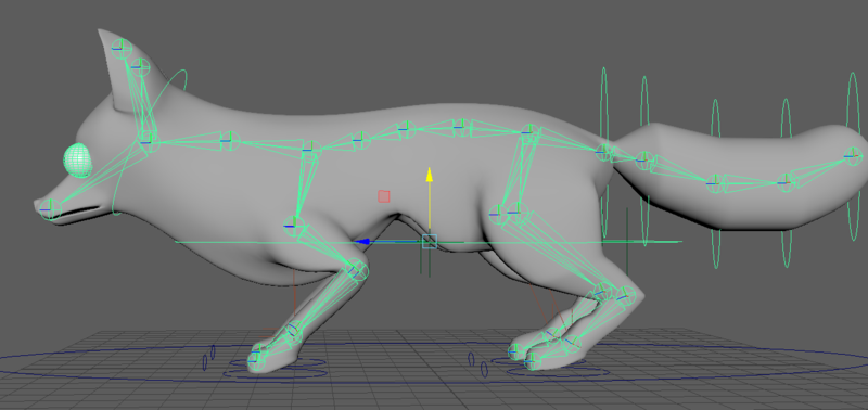
Moving the COG controller downwards, you’ll notice that a dent forms in the chest. This is a result of the elbows having influence over the chest mesh.
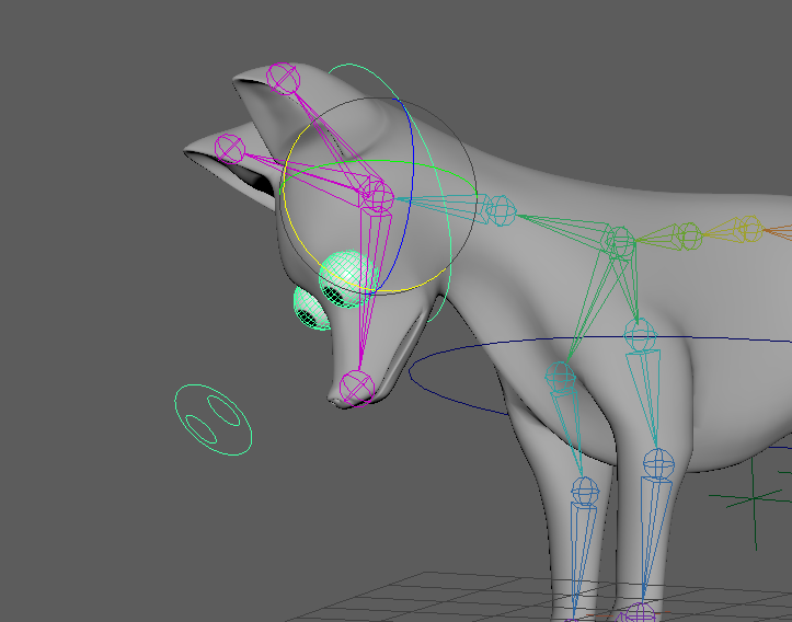
Moving the head around will reveal some weird neck stretching.
Not quite what we’re hoping for. In all of these cases, joints are effecting more of the mesh than they ought to. Luckily, we have tools that allow us to be more specific with how much mesh each joint controls. Unluckily, the process can be a bit tedious. The time invested in good skinning will certainly pay off and keep your characters from going noodly.
Check out the Skinning Guide to learn how to refine a character’s skin weights. Use this guide to make the characters for your short a bit more easy to animate.
Double check to make sure everything was frozen properly and all your new controllers have names which help convey their location and purpose.
We will NOT require that you refine the skinning on the fox. You’re welcome to try for practice but even with the techniques described in the lab above, skinning a low-poly character can be very difficult. We’d prefer if you invested that time into improving the rigs/skinning of the characters in your animation.
If you want to, you can experiment by adding controllers to the ears or explore some of the techniques listed on the next page.
ADDITIONAL STEPS - LIMITS + MORE/BETTER CONTROLLERS
At several points in the lab, more effective ways of rigging were hinted at. One way to make your rig more convenient for animators is to reduce the ways you can move controllers to only the ones that matter. IK controllers can be limited to movement and have their rotation locked. This way, animators won’t confuse which kind of control they need. You can lock certain transformations by going to the channel box. Right clicking a channel like “Rotate X” will give you an option to lock the selected channel. You can highlight several channels at once and then right click to lock them all at the same time.
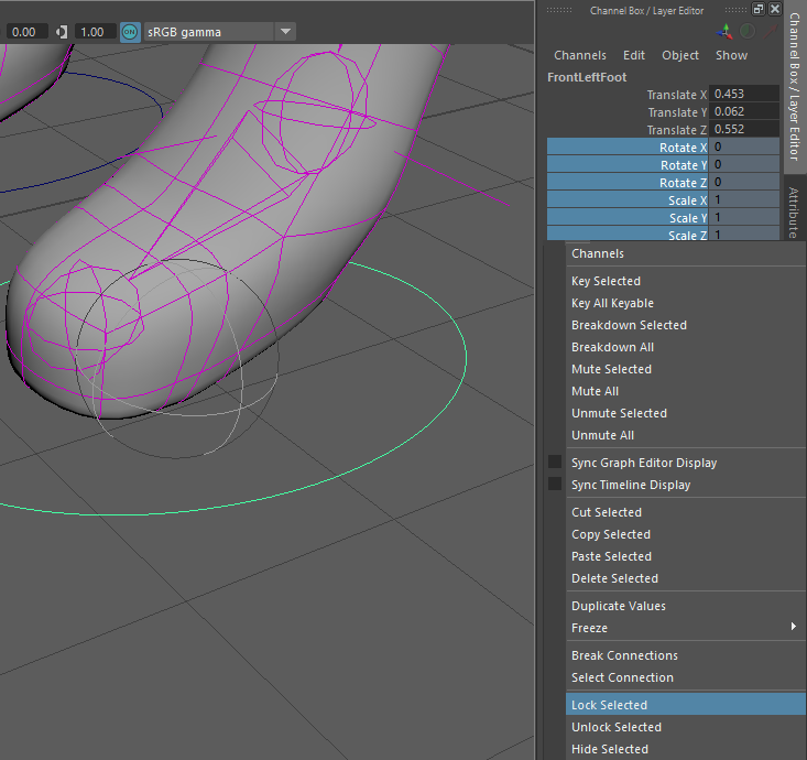
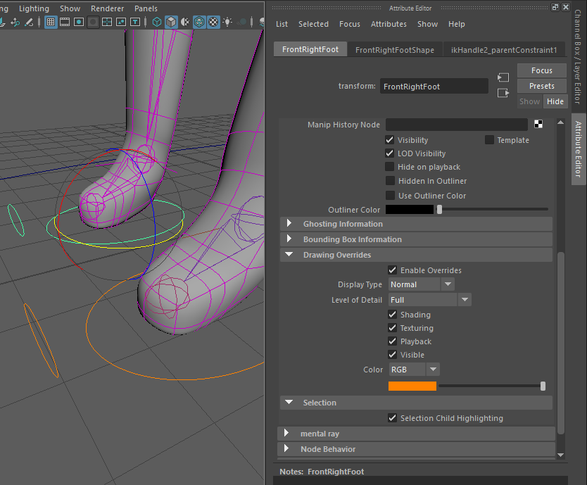
Distinguishing controllers from each other and helping the animator identify what it controls are both important principles. The advanced rigging lab teaches you how to create custom NURBS shapes which are easier to click and convey more information. One easy way to help convey differences in controllers is with color. Select a controller and open the first tab in the outliner. Scroll down and expand both the “Display” and “Drawing Overrides” tabs. By enabling overrides, you can change the color of the NURBS shapes. Try to pick colors that won’t be confused with other indicators (such as the selection green). You can use this to convey whether the controller moves an IK or a joint, which side of the rig it’s on, or simply to distinguish it in a line of other controllers (like on FK’s). Use these changes in moderation. Otherwise, your rainbow rig will be even more confusing than when it started.