INTRODUCTION
This week we’ll be rigging the fox you modeled last week! Just in case, here’s a link to a clean fox model that you can download:
I’m having trouble downloading the file…
If downloading the Maya file does not work:
- You may need to right click, hit “Save link as …”.
- If it takes you to a new page filled with text just right click on that page and “Save as”.
- If the file downloaded ends in “.ma.txt” or anything other than “.ma” rename it to have just “.ma” and ignore the warning.
The idea behind rigging is to give your model joints which will dictate how the mesh will deform. Much like how your elbow allows your arm to bend in half.
Note On This Lab
I kept the fox rig very blocky for the sake of a demonstration so it may not deform as smoothly as expected. Your models will be more detailed than this poor fox and as a result will deform more naturally so don’t be surprised if this fox “moves” strangely at the end of the lab.
SETTING UP THE MODEL
First, to get set up, you’ll want to be in side view mode to help have more control over the placement of joints. You might also want to turn on x-ray shading by going into Shading → X-Ray. This will help you see your joints through your mesh.
Next, make sure that you’re in the Rigging menu. On to top left, there is a dropdown menu that says Modeling. You’ll want to switch that to Rigging.
Before rigging, you also need to make sure your character mesh is clean by freezing transformations and deleting history.
My mesh has blendshapes already…
If your mesh DOES use blendshapes, instead of doing the normal Delete History
Edit → Delete By Type → History, a.k.a. the shortcut button at the top), you will want to instead useEdit → Delete By Type → Non-Deformer History. The reason we do this instead is because blendshapes counts as a deformer, and if you do the normalDelete By Type → History, you will lose your blendshapes.Otherwise, be sure to prepare your mesh for rigging by doing Freeze Transformations and
Delete by Type → History(again, only if you don’t have blendshapes).
SUPER IMPORTANT
Make sure to create copies of your final mesh because a messed up rig can cause corruptions.
CREATING JOINTS
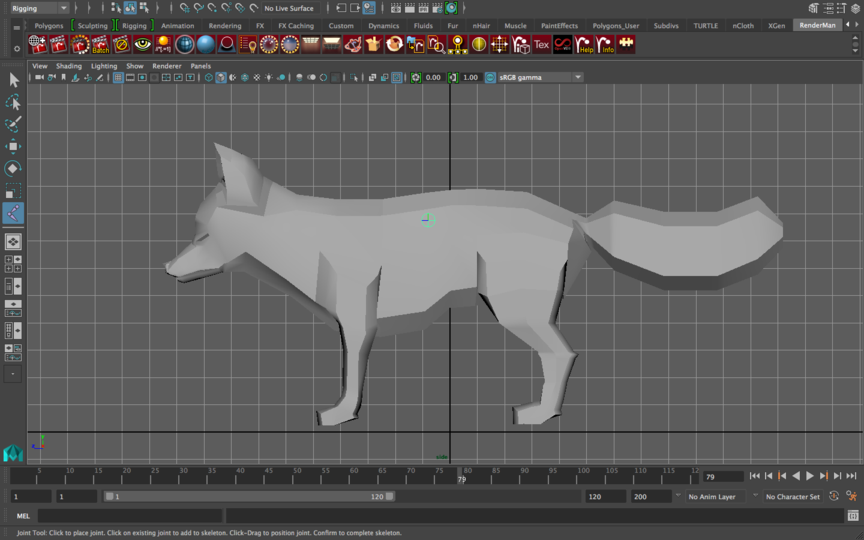
To do the first step, click Skeleton → Create Joint and put the first joint around the center of the fox like below. This will be where all the rest of the joints come from and is often called as the Center of Gravity or Root joint. Notice that the joint is placed around where the spine of the fox is and not the very center of its torso. You’ll often find that rigging follows very closely with the natural anatomy of whatever it is you’re rigging.
When I create joints, they are too small or large…
You can go to
Display → Animation → Joint Size...and adjust the slider to change how big or small ALL joints look visually.
Continue to add joints forward like so. If you click “enter” the joint creation mode will end, and the joint chain you made will end. To keep adding to the same chain (if for example you accidentally thought you were done but realized you wanted to add more to it) go to Skeleton → Create Joints and click one of the joints you already made. Now whenever you click, another joint chain will grow out of the one you previously had. This will be applied in the following step:
Observe how the head joint has two joints coming out from it. That’s done by clicking the head joint to create a connecting joint from head to nose then by pressing “enter” to cancel that connection. Go to Skeleton → Create Joints again, click the head joint and then create the ear joint.
For now, don’t worry about making 2 ear joints because we’ll be mirroring our joints.
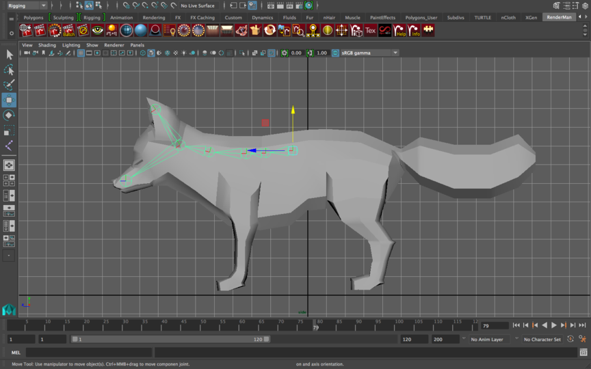
Do the same thing here. Starting from the Center of Gravity/Root joint (the first joint you created), start creating joints that reach to the end of the fox. Notice that the joint placements are strategically placed to help us animate.
For example, the beginning of the tail has a joint because we want the entire tail to have full degree of movement. The tail also has quite a number of joints because we know it’s going to be quite active. On the other hand, the face only has the one joint from head to nose. That’s because we know the head won’t move fluidly like a tail and has restricted movement.
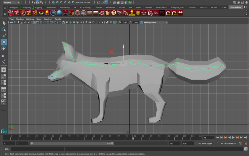
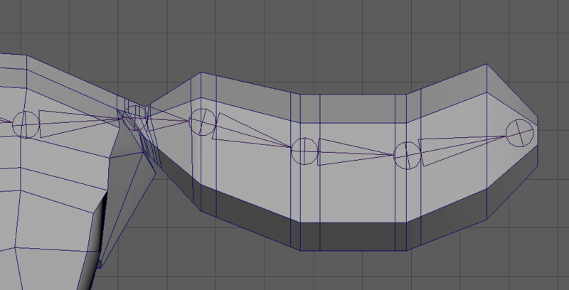
As mentioned in lecture, notice how the tail joints match the position of the edge loops. This will make the movement very fluid when we come to animate the tail.
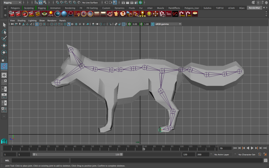
Now to create the back leg, start by clicking the “hip” joint and begin creating joints along the center of the leg. Follow the orientation of the leg like so creating joints for the knee, ankle, and to the toes.
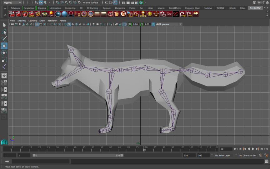
Do the same for the front leg, like so.
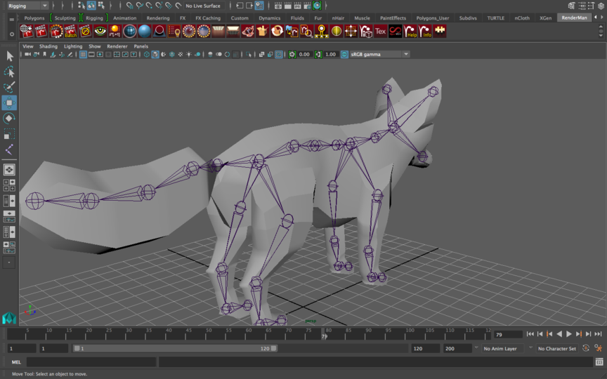
Now we’ve been working entirely in side view mode which puts our joints right at the center. This is convenient for our spine and face joints but you can see in perspective mode how the ear and leg joints are way off.
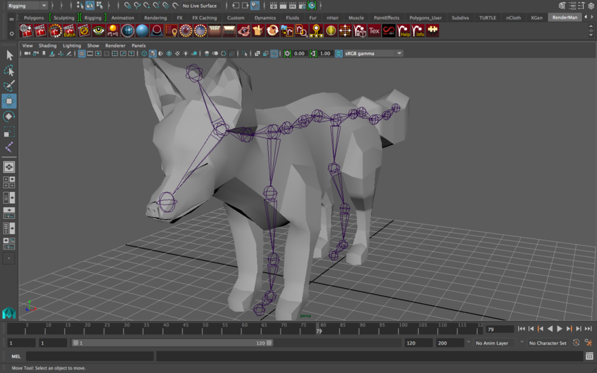
We already know from the side view mode that the joints are oriented correctly in the YZ-axis so be careful to move the joints along the correct axis. For me, that happened to be the x-axis so I moved the joints across the X-axis only. Now your leg joints should look like this.
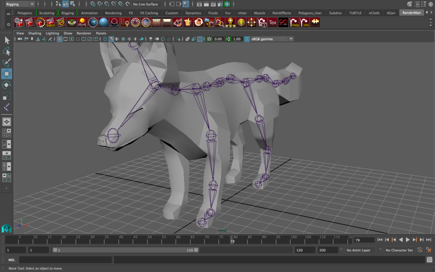
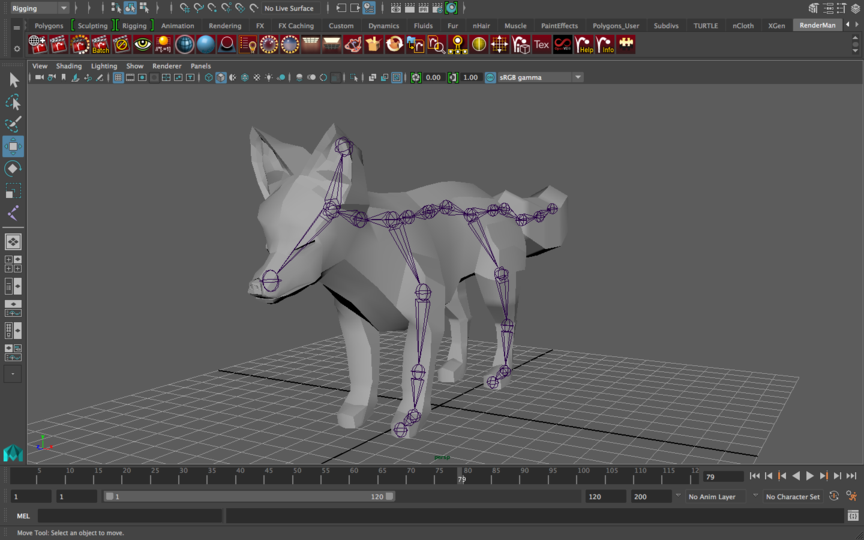
And your ear joint should be placed like this along the same axis.
MIRRORING THE JOINTS
We know our fox is symmetrical because we mirrored its geometry and we can apply the same principle to the fox’s rig!
You’ll have to mirror each limb separately.
First, select the shoulder of the front leg. That is, the first joint that comes down along the y-axis from the spine:
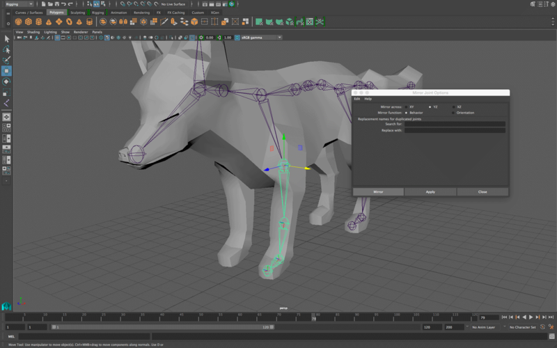
With that joint selected, go to Skeleton → Mirror Joints → Option Box.
Make sure to mirror across the correct axes. YZ worked for me but it may be different for you. Click Apply to see if your reflection was correct and change accordingly.
Do the same for the back leg and the ear.
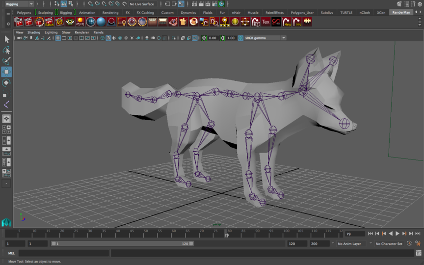
Check all angles in perspective view to make sure no joints are sticking out of the mesh or are in a bizarre location. Here’s what it looks like from behind.
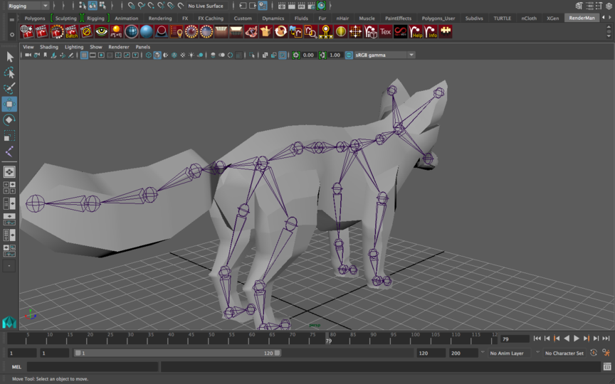
RENAMING JOINT_8
Before moving on, if you open your outliner (by going to Window → Outliner), this is what you’ll see if you expand all joints:
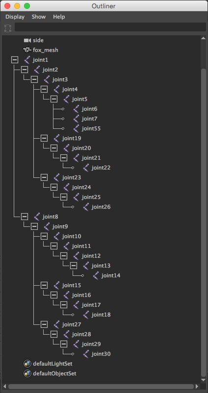
This is actually very unhelpful. Who knows what joint 8 means? Or 11? Or any of these?
Double click on every joint and rename it accordingly (i.e. right_foot; right_wrist; left_foot; left_wrist; spine_1; spine_2; etc.) so that anyone who looks at your outliner can easily understand which joint each one is. Also, if you get any errors later, Maya will reference a specific joint, and so having it say “right_foot” has some kind of error is much more helpful than “joint_18” has an error.
Now that they’re renamed, select the root joint, and go to Skeleton → Orient Joints and click the option box. Match these options and click “orient.”
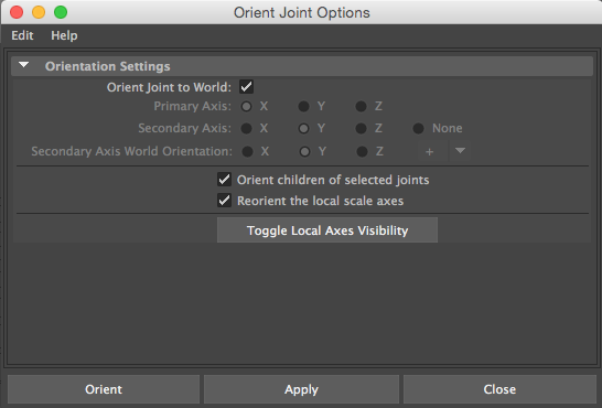
The idea behind the orient tool is that it calibrates where each joint is “facing” or pointing to. It won’t change the position of your joints, it’ll just change the directionality of them to calibrate them to the world. This could potentially fix problems when you come to the next step (or, if done incorrectly, could cause problems in the next step).
IK HANDLES
Now we’re going to attach IK handles. Recall from lecture that the IK handles allow your hierarchy of joints to move in a particular fashion as if there’s a string through your joints causing them to act upon each other.
In order to allow for IK handles to work, you’ll want to change its solver to use a Rotate Plane Solver.
Click Skeleton → Create IK Handle → Option Box and change your Current solver to Rotate Plane Solver.
This will allow your IK handle to rotate around freely when you translate.
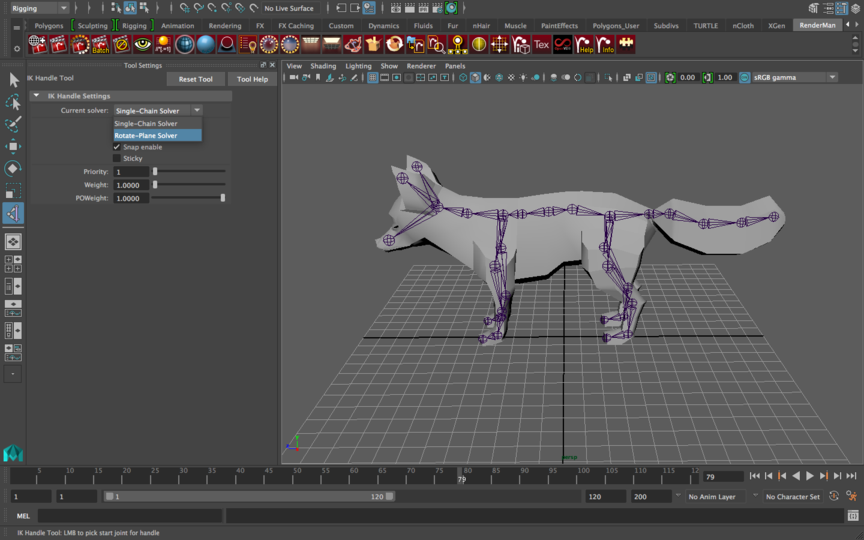
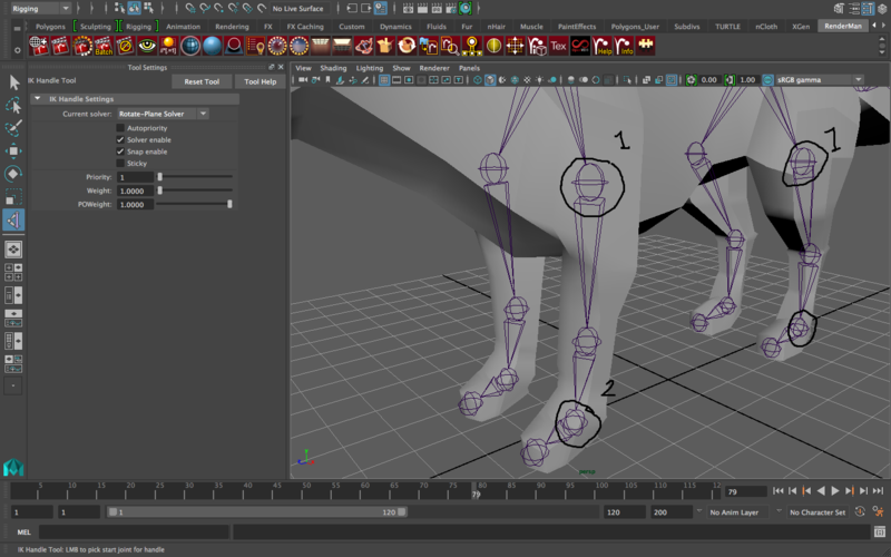
Now click the “root” of your IK handle and then the end. In this case, that’ll be the shoulder to the ankle and the hip to the ankle for the front and back legs respectively (shown in the screenshot below).
Each leg will require an IK handle but just to see/understand the difference between an IK and FK handle, play around with the legs before and after having put an IK handle in.
IK handles must always have an in-between joint like the knee between the hip and ankle joint in the leg as shown below or the elbow joint in between the shoulder and wrist.
In order to play with the IK handle, make sure you’re selecting the IK handle itself and not the ankle joint! They’ll be in the same location so it can be very tricky to notice the difference. Utilize your Outliner to ensure you’re selecting the correct component.
And you’re done with the basic rigging lab!
Currently, your rig is FAR from finished. There are a couple of final touches such as creating handles so that it’s easy to select a joint or IK handle instead of having to go into the outliner like I suggested for this lab. You also don’t have pole vectors to help you control where things like knees will point. And of course, we haven’t skinned the model so that it deforms with your rig.
The rest of the pieces needed to complete your rig will be in next week’s rigging lab. We tried to get you about halfway since you also need to worry about blendshapes this week. I hope we made this week a little less strenuous! Take it easy folks!